Dell™ PowerEdge™ 2500 Systems Installation and Troubleshooting Guide Introduction Indicators, Messages, and Codes Finding Software Solutions Running the Dell™ Diagnostics Troubleshooting Your System Installing System Board Options Installing Drives Getting Help Jumpers and Connectors Abbreviations and Acronyms Figures Tables Notes, Notices, Cautions, and Warnings NOTE: A NOTE indicates important information that helps you make better use of your computer.
Back to Contents Page Jumpers and Connectors Dell™ PowerEdge™ 2500 Systems Installation and Troubleshooting Guide Jumpers—A General Explanation System Board Jumpers System Board Connectors SCSI Backplane Board Connectors Interposer Board Connectors Disabling a Forgotten Password This section provides specific information about the jumpers on the system board. It also provides some basic information on jumpers and switches and describes the connectors and sockets on the various boards in the computer.
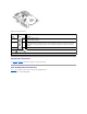
Table A-1. System-Board Jumper Settings Jumper Setting Description PASSWD (default) The password feature is enabled. The password feature is disabled. NVRAM_CLR (default) The configuration settings are retained at system boot. The configuration settings are cleared at next system boot. (If the configuration settings become corrupted to the point where the system will not boot, install the jumper plug and boot the system. Remove the jumper before restoring the configuration information.
Interposer Board Connectors Figure A-4 shows the connectors and sockets located on the interposer board. Figure A-4. Connectors on the Interposer Board Disabling a Forgotten Password The computer's software security features include a system password and a setup password, which are discussed in detail in Section 4, "Using the System Setup Program," in the User's Guide. A password jumper on the system board enables these password features or disables them and clears any password(s) currently in use.
NOTE: If you assign a new system and/or setup password with the jumper plug still removed, the system disables the new password(s) the next time it boots. 6. Repeat step 1. 7. Install the jumper plug on the PASSWD jumper. 8. Replace the right-side computer cover, and then reconnect the computer and peripherals to their electrical outlets and turn them on. 9. Assign a new system and/or setup password.
Back to Contents Page Abbreviations and Acronyms Dell™ PowerEdge™ 2500 Systems Installation and Troubleshooting Guide The following list defines or identifies technical terms, abbreviations, and acronyms used in Dell user documents. NOTE: Unless otherwise specified, these definitions may not apply to operating systems other than Microsoft® Windows® 95 and Windows NT®.
C Celsius CCFT cold cathode fluorescent tube CD compact disc CD-ROM compact disc read-only memory CGA color graphics adapter cm centimeter(s) CMOS complementary metal-oxide semiconductor C.O.D.
Deutsche Industrie Norm DIP dual in-line package DMA direct memory access DOC Department of Communications (in Canada) dpi dots per inch DRAC Dell OpenManage™ Remote Assistant Card DRAM dynamic random-access memory DS/DD double-sided double-density DS/HD double-sided high-density DSA Dell SCSI Array ECC error checking and correction EDO extended-data out EGA enhanced graphics adapter EIDE enhanced integrated drive electronics EMI electromagnetic interference EMM expanded memory manager EMS E
electrostatic discharge ESDI enhanced small-device interface ESM embedded server management F Fahrenheit FAT file allocation table FCC Federal Communications Commission FIFO first-in first-out ft feet g gram(s) G gravities GB gigabyte(s) GUI graphical user interface h hexadecimal HIP Hardware Instrumentation Package HMA high memory area HPFS High Performance File System Hz hertz I/O input/output ICBM inter-chassis management bus ID
identification IDE integrated drive electronics IRQ interrupt request ISA Industry-Standard Architecture JEIDA Japanese Electronic Industry Development Association K kilo- (1024) KB kilobyte(s) KB/sec kilobyte(s) per second Kb kilobit(s) Kbps kilobit(s) per second kg kilogram(s) kHz kilohertz LAN local area network lb pound(s) LCD liquid crystal display LED light-emitting diode LIF low insertion force LN load number lpi lines per inch
LVD low voltage differential m meter(s) mA milliampere(s) mAh milliampere-hour(s) MB megabyte(s) Mb megabit(s) Mbps megabit(s) per second MBR master boot record MDA monochrome display adapter MGA monochrome graphics adapter MHz megahertz MMX™ MultiMedia eXtensions mm millimeter(s) ms millisecond(s) MS-DOS® Microsoft Disk Operating System MTBF mean time between failures mV millivolt(s) NIC network interface controller NiCad nickel cadmium
NiMH nickel-metal hydride NMI nonmaskable interrupt NNM Network Node Manager ns nanosecond(s) NTFS NT File System NVRAM nonvolatile random-access memory OS/2® Operating System/2 OTP one-time programmable PAL programmable array logic PCI Peripheral Component Interconnect PCMCIA Personal Computer Memory Card International Association PGA pin grid array POST power-on self-test ppm pages per minute PQFP plastic quad flat pack PSDB power-supply distribution board PS/2 Personal System/2 PVC poly
RAID redundant arrays of independent disks RAM random-access memory RAMDAC random-access memory digital-to-analog converter RCU Resource Configuration Utility REN ringer equivalence number RFI radio frequency interference RGB red/green/blue ROM read-only memory rpm revolutions per minute RTC real-time clock SCA Single Controller Architecture SCSI small computer system interface SDS Scalable Disk System sec second(s) SEC single-edge contact SDRAM synchronous dynamic random-access memory SIMM
SRAM static random-access memory SSU system setup utility SVGA super video graphics array TFT thin film transistor tpi tracks per inch TSR terminate-and-stay-resident UMB upper memory block UPS uninterruptible power supply USOC Universal Service Ordering Code V volt(s) VAC volt(s) alternating current VDC volt(s) direct current VESA® Video Electronics Standards Association VGA video graphics array VLSI very-large-scale integration VRAM video random-access memory VRM voltage regulator module
watt-hour(s) X XMM extended memory manager XMS eXtended Memory Specification Z ZIF zero insertion force Back to Contents Page
Back to Contents Page Introduction Dell™ PowerEdge™ 2500 Systems Installation and Troubleshooting Guide Other Documents You May Need Getting Help Safety, Regulatory, and Warranty Information Dell™ PowerEdge™ 2500 systems are high-speed servers that offer significant service and upgrade features.
Back to Contents Page
Back to Contents Page Indicators, Messages, and Codes Dell™ PowerEdge™ 2500 Systems Installation and Troubleshooting Guide Bezel Indicators System Messages Front-Panel Indicators and Features System Beep Codes Back-Panel Features Warning Messages SCSI Hard-Disk Drive Indicator Codes Diagnostics Messages Redundant Power Supply Features Alert Log Messages From the Dell OpenManage Server Agent Applications, operating systems, and the system itself are capable of identifying problems and alerting yo
Back-Panel Features Figure 2-3 shows the back-panel features of the non-redundant AC power version of the system. Figure 2-3. Back-Panel Features SCSI Hard-Disk Drive Indicator Codes If you have the integrated RAID controller activated, or an optional PERC 3/Di controller is installed in the system, three indicators on each of the hard-disk drive carriers provide information on the status of the SCSI hard-disk drives (see Table 2-1).
Table 2-1 lists the drive indicator patterns established by the SCSI backplane firmware. Different patterns are displayed as drive events occur in the system. For example, in the event of a hard-disk drive failure, the "drive failed" pattern appears. After the drive is selected for removal, the "drive being prepared for removal" pattern appears, followed by the "drive ready for insertion or removal" pattern.
Table 2-2. Power Supply Indicator Patterns Indicator Indicator Code Power-on Green indicator indicates that the power supply is operational. Fault Red indicator indicates a problem with the power supply i.e., fan failure, voltage error, etc. AC present Green indicator indicates that AC power is present at the power supply and that the system is connected to an AC source.
assistance. Bad command or file name Command entered does not exist, is faulty, or is not in pathname specified. Faulty command and syntax, or incorrect filename. Bad error-correction code(ECC) on disk read Faulty diskette/CD-ROM subsystem or hard-disk drive subsystem (defective system board) Replace the system board. See "Getting Help," for instructions on obtaining technical assistance.
Invalid CPU speed detected Microprocessor not supported by system Install a correct version of the microprocessor in the specified microprocessor connector. See "Adding or Replacing a Microprocessor" in "Installing System Board Options." Invalid NVRAM configuration, resource reallocated System detected and corrected a resource conflict when system resources were allocated using the System Setup program. No action is required.
Reset failed Improperly connected diskette/CDROM, hard-disk drive, or power cable ROM bad checksum = address Expansion card improperly installed or Reinstall the expansion cards. See "Installing an Expansion Card" in faulty "Installing System Board Options." If the problem persists, replace the expansion card. See "Removing an Expansion Card" in "Installing System Board Options." If the problem still persists, replace the system board.
Write fault Faulty diskette or hard-disk drive Replace the diskette or hard-disk drive. See "Installing Drives." Write fault on selected drive NOTE: For the full name of an abbreviation or acronym used in this table, see "Abbreviations and Acronyms." System Beep Codes When an error that cannot be reported on the monitor occurs during a boot routine, the system may emit a series of beeps that identify the problem.
3-3-2 System configuration check failure Replace the system board. See "Getting Help," for instructions on obtaining technical assistance. 3-3-3 Keyboard controller not detected Replace the system board. See "Getting Help," for instructions on obtaining technical assistance. 3-3-4 Screen initialization failure Run the video test in the Dell Diagnostics.
Back to Contents Page Finding Software Solutions Dell™ PowerEdge™ 2500 Systems Installation and Troubleshooting Guide Installing and Configuring Software Using Software Because most systems have several application programs installed in addition to the operating system, isolating a software problem can be confusing. Software errors can also appear to be hardware malfunctions at first.
monitor may require a special screen driver program that expects a certain kind of video mode or monitor. In such cases, you may have to develop an alternate method of running that particular program—by creating a start-up file made especially for that program, for example. Call the support service for the software you are using to help you with this problem. Avoiding Interrupt Assignment Conflicts Problems can arise if two devices attempt to use the same IRQ line.
Back to Contents Page Running the Dell™ Diagnostics Dell™ PowerEdge™ 2500 Systems Installation and Troubleshooting Guide Features of the Dell Diagnostics How to Use the Device Groups Menu When to Use the Dell Diagnostics Device Groups Menu Options Starting the Dell Diagnostics Error Messages How to Use the Dell Diagnostics Unlike many diagnostic programs, the Dell Diagnostics helps you check the system's hardware without any additional equipment and without destroying any data.
If the system fails to boot, see "Getting Help," for instructions on obtaining technical assistance. When you start the diagnostics a message is displayed telling you that the diagnostics is loading. The Diagnostics menu appears. The menu allows you to run all or specific diagnostic tests or to exit the Dell Diagnostics. NOTE: Before you read the rest of this section, you may want to start the Dell Diagnostics so that you can see it on your monitor screen.
Most of the device groups consist of several devices. Use the Devices option to select individual devices within the device group(s). When you select Devices, the following options are displayed: Run Tests, Tests, Select, Parameters, and Help. Table 4-1 lists all of the possible values for each option. Table 4-1. Devices Options Option Functions Run Tests Displays five options: Run Tests, Tests, Select, Parameters, and Help.
Back to Contents Page Troubleshooting Your System Dell™ PowerEdge™ 2500 Systems Installation and Troubleshooting Guide Safety First—For You and Your System Troubleshooting Redundant Power Supplies External Connections Troubleshooting a Cooling Fan Checking Specific System Problems Troubleshooting Expansion Cards Start-Up Routine Troubleshooting System Memory System Orientation Troubleshooting the Video Subsystem Removing and Replacing the Front Bezel Troubleshooting the System Board Removing a
4. Is the monitor working properly? See "Troubleshooting the Video Subsystem." 5. Is the keyboard working properly? See "Troubleshooting the Keyboard." 6. Are the mouse and printer working properly? See "Troubleshooting the Basic I/O Functions." Start-Up Routine Looking at and listening to the system is important in determining the source of a problem. Look and listen during the system's start-up routine for the indication described in Table 5-1. Table 5-1.
The front bezel has status and attention indicators. Swinging the front bezel open provides access to the power switch, diskette drive, CD-ROM drive, hard-disk drive (s), and power supplies. You must open or remove the front bezel and remove the system cover to gain access to internal components. Removing the Front Bezel 1. Using the system key, unlock the front bezel. 2. Pull the bezel away from the system so that it is perpendicular to the system (see Figure 5-2). Figure 5-2.
Replacing the System Cover 1. Check that no tools or parts are left inside the system. 2. Fit the cover over the sides of the chassis, and slide the cover forward. 3. Secure the cover with the three thumbscrews. 4. Close the front bezel. Checking the Equipment This section provides troubleshooting procedures for equipment that connects directly to the I/O panel of the system, such as the monitor, keyboard, or mouse. Before you perform any of the procedures, see "External Connections.
2. Press and release each key on the keyboard. If the keyboard and its cable appear to be free of physical damage, and the keys work, go to step 4. If the keyboard or its cable are damaged, continue to step 3. 3. Swap the faulty keyboard with a working keyboard. If the problem is resolved, the keyboard must be replaced. See "Getting Help," for instructions on obtaining technical assistance. 4. Run the keyboard test in the Dell Diagnostics.
4. Swap the interface cable with a known working cable. If the problem is resolved, the interface cable must be replaced. See "Getting Help," for instructions on obtaining technical assistance. 5. Turn off the system and the serial device, and swap the device with a comparable device. 6. Turn on the power to the system and the serial device. If the problem is resolved, the serial device must be replaced.
l NIC cannot communicate with net Action 1. Enter the System Setup program and confirm that the NIC is enabled. See "Using the System Setup Program" in the User's Guide for instructions. 2. Check the two indicators on the left and right corners of the NIC connector on the system's back-panel (see Figure 5-4). The green link indicator shows that the adapter is connected to a valid link partner. The amber activity indicator lights if network data is being sent or received.
hot-pluggable redundant power supplies that are front loadable and slide into connectors mounted on the the PDB. When this option is installed, the PDB will provide power to the system board, SCSI backplane board, and internal peripherals. For non-SCSI drives such as the diskette drive and CD-ROM drive, an interface cable connects the interposer board, attached to the diskette drive and CD-ROM drive, to the system board.
Troubleshooting the System Battery Problem l Error message shows problem with the battery l System setup program loses the system configuration information l System date and time will not stay current Action 1. Check the connection of the coin cell battery to the system board. See "Replacing the System Battery" in "Installing System Board Options." WARNING: There is a danger of a new battery exploding if it is incorrectly installed.
Figure 5-6. Removing a Cooling Fan 4. Reseat the fan in its compartment. Ensure that the fan connector is firmly seated. 5. If the problem is not resolved, insert a replacement cooling fan. 6. If the replacement fan does not operate, one of the fan bay connectors is faulty. See "Getting Help," for information on obtaining technical assistance.
Repeat steps 8 and 9, and steps 11 through 13. 15. Repeat step 14 for each of the remaining expansion cards. If you have reinstalled all of the expansion cards and the system memory tests are still failing, see "Getting Help," for information on obtaining technical assistance. Troubleshooting System Memory Problem l Faulty memory module l Faulty system board Action 1. Turn on the power to the system, including any attached peripherals. If there is not an error message, go to step 8. 2.
Troubleshooting the Video Subsystem Problem l Monitor not operating l Monitor interface cable not connected correctly or is faulty l Video logic problems Action 1. Check the system and power connections to the monitor. 2. Run the video tests in the Dell Diagnostics. If the tests run successfully, the problem is not related to video hardware. See "Finding Software Solutions." If the tests did not run successfully see "Getting Help," for instructions on obtaining technical assistance.
1. Enter the system setup program, and verify that the system is configured correctly. See "Using the System Setup Program" in the User's Guide for instructions. 2. Run the diskette drive tests in the Dell Diagnostics to see whether the diskette drive now works correctly. 3. Turn off the system, including any attached peripherals, and disconnect the system from its electrical outlet. 4.
l Tape drive online indicator fails to light after operating system installs Action 1. Remove the tape that was in use when the problem occurred and replace it with a tape that you know is not defective. 2. Verify that any required SCSI device drivers are installed on the hard-disk drive and are configured correctly. 3.
6. Check the SCSI cable connections inside the system: a. Turn off the system, including any attached peripherals, and disconnect the system from its electrical outlet. b. Remove the system cover. c. Check the SCSI cable connection to the SCSI host adapter. The SCSI cable may be connected to the internal SCSI host adapter on the system board or a SCSI host adapter installed in an expansion slot. NOTE: If the SCSI cable is connected to the SCSI channel A only, all six hard-disk drives are controlled.
Back to Contents Page
Back to Contents Page Installing System Board Options Dell™ PowerEdge™ 2500 Systems Installation and Troubleshooting Guide Removing and Replacing Fan Assemblies Adding Memory Expansion Cards Microprocessor Upgrades Removing and Installing the Cooling Shroud Activating the Integrated RAID Controller Removing and Installing a Power Supply Replacing the System Battery This section describes how to install the following options: l Expansion cards l Memory upgrades l Microprocessor upgrades l In
DIMM_x Memory module sockets (A–F) DIMM_RAID Memory module socket for integrated RAID controller ENET Ethernet connector REAR FAN Power for the rear fan assembly FLOPPY/IDE Power and data to the diskette/CD ROM interposer board from the system board INTR Intrusion-alarm switch connectors KYBD Keyboard connector MOUSE Mouse connector FRONT PANEL System control panel connector PARALLEL Parallel port connector; sometimes referred to as LPT1 POWERn Power connector PROCESSOR_n Microprocess
2. Place the fan assembly in the hinge bracket and swing the fan assembly down until the release lever snaps into place. 3. Replace the system cover. 4. Close the front bezel. Removing the Back Fan Assembly 1. Open the front bezel (see "Removing the Front Bezel" in "Troubleshooting Your System"). 2. Remove the system cover. 3. Remove the cooling shroud (see "Removing the Cooling Shroud"). 4. Press the release latch and lift the fan assembly straight up to clear the chassis (see Figure 6-3).
To replace a fan: 1. Lower the fan into the fan assembly until the fan snaps into position. 2. Replace the system cover. 3. Close the front bezel. Expansion Cards Expansion cards are installed on the system board (see Figure 6-1). There are seven expansion card slots available. The front fan assembly bracket is used to help secure the expansion cards. Installing an Expansion Card To install an expansion card, perform the following steps.
9. When the card is seated in the connector and the card-mounting bracket is aligned with the brackets on either side of it, close the expansion-card latch. NOTE: SCSI cables connected from an expansion card to the SCSI backplane board should be routed under the front fan assembly. 10. Connect any cables that should be attached to the card. See the documentation that came with the card for information about its cable connections. 11.
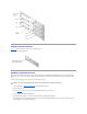
3. Loosen the two thumbscrews securing the cooling shroud to the system (see Figure 6-6). Figure 6-6. Removing and Installing the Cooling Shroud 4. Rotate the cooling shroud up and lift to clear the rear cooling fan assembly and chassis (see Figure 6-7). Figure 6-7. Rotating the Cooling Shroud Installing the Cooling Shroud 1. Lower the cooling shroud into the chassis ensuring that the cooling shroud is aligned with the rear cooling fan assembly guides. 2.
2. Remove the power supply by grasping the power supply handle, pressing down on the release lever, and pulling the power supply straight out to clear the chassis (see Figure 6-8). Figure 6-8. Removing and Installing the Power Supply 3. Install the power supply by sliding the new power supply into the chassis until it snaps into place. 4. Close the front bezel. Adding Memory The six memory module sockets on the system board can accommodate 128 MB to 4 GB of registered SDRAM.
Table 6-2 illustrates several sample memory configurations based on these guidelines. Table 6-2. Sample Memory Module Configurations Total Desired Memory DIMM_A DIMM_B DIMM_C DIMM_D DIMM_E DIMM_F 128 MB 64 MB 64 MB None None None None 256 MB 128 MB 128 MB None None None None 512 MB 256 MB 256 MB None None None None 512 MB 128 MB 128 MB 128 MB 128 MB None None 1 GB 256 MB 256 MB 256 MB 256 MB None None 1.
Press to continue; to enter System Setup 8. Press to enter the System Setup program, and check the System Memory setting in the system data box on the System Setup screens. The system should have already changed the value in the System Memory setting to reflect the newly installed memory. 9. If the System Memory value is incorrect, one or more of the memory modules may not be installed properly.
2. Remove the system cover. 3. Remove the cooling shroud (see "Removing the Cooling Shroud"). 4. Locate the memory module sockets in which you will remove memory modules. Figure 6-9 shows the order of the memory module sockets. 5. Press down and outward on the ejectors on each end of the socket until the memory module pops out of the socket (see Figure 6-11). Figure 6-11.
maintain proper thermal conditions. WARNING: The microprocessor chip and heat sink can become extremely hot. Be sure the microprocessor has had sufficient time to cool before handling. Figure 6-12. Securing Clip 6. Remove the heat sink. 7. Pull the socket release lever straight up until the microprocessor is released (see Figure 6-13). 8. Lift the microprocessor out of the socket and leave the release lever up so that the socket is ready for the new microprocessor.
triangle points toward pin 1, which is also uniquely identified by a square pad. Figure 6-14. Pin-1 Identification 11. Install the microprocessor in the socket (see Figure 6-15). CAUTION: Positioning the microprocessor incorrectly can permanently damage the microprocessor and the system when you turn on the system. When placing the microprocessor in the socket, be sure that all of the pins on the microprocessor go into the corresponding holes. Be careful not to bend the pins.
14. Hook the end of the clip without the heat-sink latch to the tab on the edge of the socket facing the front of the system. 15. Push down and pivot the heat-sink latch until the hole on the clip latches onto the ZIF socket tab. CAUTION: If you are installing a VRM, it must be a +12V VRM. 16. If you are adding a second microprocessor, place the VRM in the socket (see Figure 6-17). 17. Make sure that the latches engage. Figure 6-17. Installing the VRM 18.
NOTE: After you remove and replace the front bezel, the chassis intrusion detector will cause the following message to be displayed at the next system start-up: ALERT! Bezel was previously removed. 24. Enter the System Setup program, and confirm that the top line in the system data area correctly identifies the installed processor(s). See "Using the System Setup Program" in your User's Guide. 25. While in the System Setup program, reset the chassis intrusion detector.
Insert the hardware key into the socket and secure the key with the latches on each end of the socket (see Figure 6-19). Figure 6-19. Installing the RAID Key 8. Install the RAID battery (see "Installing the RAID Battery"). 9. Replace the cooling shroud and system cover; reconnect the system and peripherals to their power sources and turn them on. 10. Install the RAID software. For details, see the RAID controller documentation. Installing the RAID Battery 1.
Replacing the System Battery The system battery maintains system configuration, date, and time information in a special section of memory when you turn off the system. The operating life of the battery ranges from 2 to 5 years, depending on how you use the system (for example, if you keep the system on most of the time, the battery gets little use and thus lasts longer).
1. Enter the System Setup program and, if possible, make a printed copy of the System Setup screens. See "Using the System Setup Program," in the User's Guide for instructions. 2. Shut down the system, including any attached peripherals, and disconnect the system from the electrical outlet. CAUTION: See "Protecting Against Electrostatic Discharge" in the safety instructions in your System Information document. 3. Open the front bezel (see "Removing the Front Bezel" in "Troubleshooting Your System").
Back to Contents Page Installing Drives Dell™ PowerEdge™ 2500 Systems Installation and Troubleshooting Guide Removing the Peripheral Bay Connecting an External SCSI Tape Drive Installing the Peripheral Bay Installing SCSI Hard-Disk Drives Interface Cables Installing a Dell Host Adapter Card SCSI Configuration Information Installing a SCSI Backplane Daughter Card Installing a Device That Uses the System's Integrated SCSI Controller Configuring the Boot Device Installing a Tape Drive That Uses a C
3. Align the tabs on side of the peripheral bay with the locking slots in the chassis and slide the peripheral bay forward. 4. Tighten the thumbscrew securing the peripheral bay to the chassis (see Figure 7-1). 5. Replace the front fan assembly (see "Replacing the Front Fan Assembly" in "Installing System Board Options"). 6. Replace the system cover. 7. Close the front bezel.
From the inside of the chassis, push outwards on the center of the insert to remove the insert from the chassis. 7. Remove the peripheral bay (see "Removing the Peripheral Bay"). 8. Slide the new drive into the peripheral bay until the holes in the peripheral bay and the drive line up. 9. Using four screws, secure the drive to the peripheral bay. 10. Install the peripheral bay (see "Installing the Peripheral Bay"). 11. Connect the SCSI device to the SCSI cable provided with the device.
system board. Route the SCSI cable along the top of the cooling shroud. 14. Check all cable connections that may have been loosened during this procedure. Arrange cables so that they will not catch on the system cover or block the airflow of the fans or cooling vents. 15. Replace the system cover. 16. Close the front bezel. 17. Reconnect the system and peripherals to their power sources, and turn on the power. 18.
NOTE: Dell recommends that you use only drives that Dell has tested and approved for use with the SCSI backplane board. Refer to the following guidelines when you configure the SCSI drive: l Disable termination on the drive. The SCSI backplane board provides termination for the SCSI bus. l Set the SCSI ID on all drives to 0. All SCSI ID numbers for the drives are set by the SCSI backplane board.
for removal. 3. Open the front bezel (see "Removing the Front Bezel" in "Troubleshooting Your System"). 4. Open the drive carrier handle to release the carrier. 5. Slide the carrier toward you until it is free of the drive bay. 6. Close the front bezel. Installing a Dell Host Adapter Card Follow these general guidelines when installing a Dell host adapter card. For specific instructions, see the documentation supplied with the host adapter card.
3. Open the front bezel (see "Removing the Front Bezel" in "Troubleshooting Your System"). 4. Remove the system cover. 5. The daughter card fits between the sides of a card guide on the top of the drive bay. To install the card in the card guide: a. Hold the daughter card by its edges with the component side facing up and the card connector facing the SCSI backplane board (see Figure 7-3). b. Ensure that the retention lever is in the open position. Figure 7-3.
Back to Contents Page Getting Help Dell™ PowerEdge™ 2500 Systems Installation and Troubleshooting Guide Help Overview Dell Contact Numbers Help Overview This section describes the tools Dell provides to help you when you have a problem with your computer. It also tells you when and how to contact Dell for technical or customer assistance. Technical Assistance If you need assistance with a technical problem, perform the following steps: 1. Complete the procedures in "Troubleshooting Your System." 2.
l Electronic Support Service support@us.dell.com apsupport@dell.com (for Asian/Pacific countries only) support.euro.dell.com (for Europe only) l Electronic Quote Service sales@dell.com apmarketing@dell.com (for Asian/Pacific countries only) l Electronic Information Service info@dell.com AutoTech Service Dell's automated technical support service—AutoTech—provides recorded answers to the questions most frequently asked by Dell customers about their portable and desktop computer systems.
4. Include any accessories that belong with the item(s) being returned (such as power cables, software diskettes, and guides) if the return is for credit. 5. Pack the equipment to be returned in the original (or equivalent) packing materials. You are responsible for paying shipping expenses. You are also responsible for insuring any product returned, and you assume the risk of loss during shipment to Dell. Collect-on-delivery (C.O.D.) packages are not accepted.
NOTE: Toll-free numbers are for use only within the country for which they are listed. Area codes are most often used to call long distance within your own country (not internationally)—in other words, when your call originates in the same country you are calling.
Chile (Santiago) Sales (Major Accounts) toll free: 1-800-387-5755 TechFax toll free: 1-800-950-1329 Sales, Customer Support, and Technical Support toll free: 1230-020-4823 Country Code: 56 City Code: 2 China (Xiamen) Country Code: 86 City Code: 592 Czech Republic (Prague) International Access Code: 00 Country Code: 420 City Code: 2 Technical Support toll free: 800 858 2437 Customer Experience toll free: 800 858 2060 Home and Small Business toll free: 800 858 2222 Preferred Accounts Division
Website: http://support.euro.dell.com E-mail: web_fr_tech@dell.
Faxbox Service 044 556-3490 Switchboard 044 556-4300 Website: http://support.jp.dell.com Korea (Seoul) International Access Code: 001 Technical Support toll free: 080-200-3800 Sales toll free: 080-200-3777 Customer Service (Seoul, Korea) Country Code: 82 City Code: 2 Customer Service (Penang, Malaysia) Fax Switchboard Latin America 2194-6220 604 633 4949 2194-6202 2194-6000 Customer Technical Support (Austin, Texas, U.S.A.) 512 728-4093 Customer Service (Austin, Texas, U.S.A.
E-mail: tech_nl@dell.
Customer Care 902 118 546 Switchboard 91 722 92 00 Fax 91 722 95 83 Website: http://support.euro.dell.com E-mail: web_esp_tech@dell.com Sweden (Upplands Vasby) International Access Code: 009 Country Code: 46 City Code: 8 Technical Support 08 590 05 199 Relational Customer Care 08 590 05 642 Home/Small Business Customer Care 08 587 70 527 Fax Technical Support 08 590 05 594 Sales 08 590 05 185 Website: http://support.euro.dell.com E-mail: swe_support@dell.
Numbers) Public Americas International (systems purchased by governmental agencies [local, state, or federal] or educational institutions): Customer Service and Technical Support (Return Material Authorization Numbers) toll free: 1-800-234-1490 Dell Sales toll free: 1-800-289-3355 or toll free: 1-800-879-3355 Spare Parts Sales toll free: 1-800-357-3355 DellWare™ toll free: 1-800-753-7201 Desktop and Portable Fee-Based Technical Support toll free: 1-800-433-9005 Server Fee-Based Technical Support
Back to Contents Page Dell™ PowerEdge™ 2500 Systems Installation and Troubleshooting Guide Notes, Notices, Cautions, and Warnings Notes, Notices, Cautions, and Warnings NOTE: A NOTE indicates important information that helps you make better use of your computer. NOTICE: A NOTICE indicates either potential damage to hardware or loss of data and tells you how to avoid the problem. CAUTION: A CAUTION indicates a potentially hazardous situation which, if not avoided, may result in minor or moderate injury.
Back to Contents Page Figures Dell™ PowerEdge™ 2500 Systems Installation and Troubleshooting Guide Figure2-1. Bezel Indicators Figure2-2. Front-Panel Features Figure2-3. Back-Panel Features Figure2-4. Hard-Disk Drive Indicators Figure2-5. Power Supply Features Figure5-1. System Orientation Figure5-2. Removing the Front Bezel Figure5-3. Removing the System Cover Figure5-4. NIC Indicators Figure5-5. Inside the System Figure5-6. Removing a Cooling Fan Figure6-1. System Board Features Figure6-2.
Back to Contents Page Tables Dell™ PowerEdge™ 2500 Systems Installation and Troubleshooting Guide Table 2-1. SCSI Hard-Disk Drive Indicator Patterns Table 2-2. Power Supply Indicator Patterns Table 2-3. System Messages Table 2-4. System Beep Codes Table 3-1. IRQ Line Assignment Defaults Table 4-1. Devices Options Table 4-2. Parameters Options Table 5-1. Start-Up Routine Indications Table 6-1. System Board Connectors and Sockets Table 6-2. Sample Memory Module Configurations Table A-1.