
User Manual


Cabling Instructions for the –48 VDC 1-3
To construct the DC input power cable, perform the following steps:
1 Strip the insulation from the ends of the six DC power wires, exposing approximately
4.5 mm (0.175 inches) of copper wire.
2 Using a hand-crimping tool, crimp a connector contact to each DC power wire.
3 Slide a piece of heat-shrink tubing over the DC power cable.
The heat-shrink tubing should be approximately 3.175 cm (1.25 inches) in length.
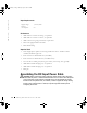
4 Insert the three black –48 VDC wires into connector housing positions 2, 3, and 6 (see
Figure 1-1 and Table 1-1).
5 Insert the three red –48 VDC return wires into connector housing positions 1, 4, and 5
(see Figure 1-1 and Table 1-1).
6 Slide the heat-shrink tubing over the DC power cable so that it overlaps the connector
housing by at least 6.35 mm (0.25 inches).
7 Using a heat gun, shrink the tubing around the cable and connector housing.
Figure 1-1. Connector Housing
Table 1-1. Connector Housing Pin Assignments
Pin Description Wire Color and Size
1 –48 VDC return Red 16 AWG
2–48 VDC Black 16 AWG
3–48 VDC Black 16 AWG
4 –48 VDC return Red 16 AWG
5 –48 VDC return Red 16 AWG
6–48 VDC Black 16 AWG
1
2
36
5
4
front view
0R216bk0.book Page 3 Monday, April 8, 2002 1:25 PM