
Instruction Manual


Keyboard and Mouse Connectors
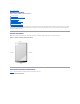
The system supports a PS/2-compatible keyboard and mouse. Cables from both devices attach to 6-pin, miniature Deutsche Industrie Norm (DIN) connectors
on the back panel of the system.
Mouse driver software can give the mouse priority with the microprocessor by issuing IRQ12 whenever a new mouse movement is detected. The driver
software also passes along the mouse data to the application program that is in control.
Keyboard and Mouse Connectors
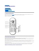
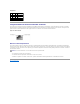
If you reconfigure your hardware, you may need pin number and signal information for the keyboard connector or mouse connector. FigureB-4 illustrates the
pin numbers for the keyboard and mouse connectors and TableB-3 defines the pin assignments and interface signals for the keyboard and mouse connectors.
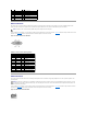
Figure B-4. Keyboard and Mouse Connector Pin Numbers
Table B-2. Parallel Connector Pin
Assignments
Pin
Signal
I/O
Definition
1
STB#
I/O
Strobe
2
PD0
I/O
Printer data bit 0
3
PD1
I/O
Printer data bit 1
4
PD2
I/O
Printer data bit 2
5
PD3
I/O
Printer data bit 3
6
PD4
I/O
Printer data bit 4
7
PD5
I/O
Printer data bit 5
8
PD6
I/O
Printer data bit 6
9
PD7
I/O
Printer data bit 7
10
ACK#
I
Acknowledge
11
BUSY
I
Busy
12
PE
I
Paper end
13
SLCT
I
Select
14
AFD#
O
Automatic feed
15
ERR#
I
Error
16
INIT#
O
Initialize printer
17
SLIN#
O
Select in
18–25
GND
N/A
Signal ground
Table B-3. Keyboard and Mouse Connector Pin
Assignments
Pin
Signal
I/O
Definition
1
KBDATA or MFDATA
I/O
Keyboard data or mouse data