Dell™ PowerEdge™ 6600 Systems Installation and Troubleshooting Guide Introduction Indicators, Messages, and Codes Finding Software Solutions Running the System Diagnostics Troubleshooting Your System Installing System Options Installing Drives Getting Help Jumpers and Connectors Abbreviations and Acronyms Notes, Notices, and Cautions NOTE: A NOTE indicates important information that helps you make better use of your computer.
Back to Contents Page Jumpers and Connectors Dell™ PowerEdge™ 6600 Systems Installation and Troubleshooting Guide Jumpers—A General Explanation I/O Riser Card Jumpers and Connectors I/O Board Connectors and Buses Microprocessor Board Connectors SCSI Backplane Board Connectors Peripheral Riser Card Connectors Disabling a Forgotten Password This section provides specific information about the jumpers on the system board.
Table A-1. I/O Riser Card Jumper Settings Jumper Setting NVRAM_CLR Description The configuration settings are retained at system boot. (default) The configuration settings are cleared at next system boot. (If the configuration settings become corrupted to the point where the system will not boot, change the jumper setting to 1–2 and boot the system. Change the jumper setting back to 2–3 before restoring the configuration information.) PSWD The password feature is enabled.
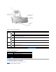
Microprocessor Board Connectors See Figure A-4 and Table A-3 for the location and description of the microprocessor board connectors. Figure A-4. Microprocessor Board Connectors Table A-3.
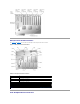
Figure A-5 shows the location of the connectors on each side of the SCSI backplane board. Figure A-5. Connectors on the SCSI Backplane Board Peripheral Riser Card Connectors See Figure A-6 and Table A-4 for the location and description of the peripheral riser card connectors. Figure A-6. Peripheral Riser Card Connectors Table A-4.
Disabling a Forgotten Password The system's software security features include a system password and a setup password, which are discussed in detail in "Using the System Setup Program" in the User's Guide. A password jumper on the I/O riser card enables these password features or disables them and clears any password(s) currently in use. To disable a forgotten system password or setup password, perform the following steps.
Back to Contents Page Abbreviations and Acronyms Dell™ PowerEdge™ 6600 Systems Installation and Troubleshooting Guide A ampere(s) AC alternating current ADC analog-to-digital converter ANSI American National Standards Institute APIC Advanced Peripheral Interrupt Controller ASIC application-specific integrated circuit BIOS basic input/output system BMC baseboard management controller bpi bits per inch bps bits per second BTU British thermal unit C Celsius CD compact disc CGA color graphics ada
characters per line CPU central processing unit DAC digital-to-analog converter DAT digital audio tape dB decibel(s) dBA adjusted decibel(s) DC direct current DDR double-data rate DIMM dual in-line memory module DIN Deutsche Industrie Norm DIP dual in-line package DMA direct memory access DOC Department of Communications (in Canada) dpi dots per inch DRAC Dell™ Remote Access Card DRAM dynamic random-access memory DS/DD double-sided double-density DS/HD double-sided high-density ECC error c
enhanced graphics adapter EIDE enhanced integrated drive electronics EMI electromagnetic interference EMM expanded memory manager EMS Expanded Memory Specification EPP Enhanced Parallel Port EPROM erasable programmable read-only memory ESD electrostatic discharge ESDI enhanced small-device interface ESM embedded server management F Fahrenheit FAT file allocation table FCC Federal Communications Commission ft feet g gram(s) G gravities GB gigabyte(s) GUI graphical user interface Hz hertz I
IDE integrated drive electronics IRQ interrupt request K kilo- (1024) KB kilobyte(s) KB/sec kilobyte(s) per second Kb kilobit(s) Kbps kilobit(s) per second kg kilogram(s) kHz kilohertz LAN local area network lb pound(s) LCD liquid crystal display LED light-emitting diode LIF low insertion force LN load number lpi lines per inch LVD low voltage differential m meter(s) mA milliampere(s) mAh milliampere-hour(s)
MB megabyte(s) Mb megabit(s) Mbps megabit(s) per second MBR master boot record MDA monochrome display adapter MGA monochrome graphics adapter MHz megahertz mm millimeter(s) ms millisecond(s) MTBF mean time between failures mV millivolt(s) NIC network interface controller NiCad nickel cadmium NiMH nickel-metal hydride NMI nonmaskable interrupt ns nanosecond(s) NTFS NT File System NVRAM nonvolatile random-access memory OTP one-time programmable PAL programmable array logic PCI
Peripheral Component Interconnect PCMCIA Personal Computer Memory Card International Association PDB power distribution board PDU power distribution board PGA pin grid array PIC personal identification code POST power-on self-test ppm pages per minute PQFP plastic quad flat pack PSDB power-supply distribution board PS/2 Personal System/2 PXE preboot execution environment RAID redundant arrays of independent disks RAM random-access memory RCU Resource Configuration Utility REN ringer equivalen
real-time clock SBE single bit ECC SCSI small computer system interface sec second(s) SEC single-edge contact SEL system event log SDRAM synchronous dynamic random-access memory SIMM single in-line memory module SMB server management bus SMI system management interrupt SNMP Simple Network Management Protocol SRAM static random-access memory SVGA super video graphics array TFT thin film transistor tpi tracks per inch UMB upper memory block UPS uninterruptible power supply USB universal seria
VGA video graphics array VLSI very-large-scale integration VRAM video random-access memory VRM voltage regulator module W watt(s) WH watt-hour(s) XMM extended memory manager XMS eXtended Memory Specification ZIF zero insertion force Back to Contents Page
Back to Contents Page Introduction Dell™ PowerEdge™ 6600 Systems Installation and Troubleshooting Guide Other Documents You May Need Obtaining Technical Assistance Your system is a high-speed server that offers significant service and upgrade features.
Back to Contents Page Indicators, Messages, and Codes Dell™ PowerEdge™ 6600 Systems Installation and Troubleshooting Guide System Status Indicators LCD Status Messages Front-Panel Indicators and Features System Messages Back-Panel Indicators and Features System Beep Codes SCSI Hard-Drive Indicator Codes Warning Messages Power-Supply Indicator Codes Diagnostics Messages NIC Indicator Codes Alert Messages Expansion-Slot Indicator Codes Applications, operating systems, and the system itself are c
Indicator Status Caution Off Off Off No power is available to the system, or the system is not powered on. On Off Blue The system is operating normally. Off Blinking Amber blinking Blinking Off Blue blinking The system has detected an error and requires attention. The system is identifying itself. NOTE: Systems management software causes the status indicator to blink to identify a particular system. For more information, see the systems management software documentation.
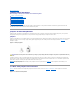
SCSI Hard-Drive Indicator Codes Each SCSI hard-drive carrier has two indicators: a busy indicator and a status indicator (see Figure 2-4). The indicators provide information on the status of the respective hard drive. Table 2-2 lists the drive indicator codes. Figure 2-4. SCSI Hard-Drive Indicators Table 2-2 lists the drive indicator codes. Different codes display as drive events occur in the system. For example, in the event of a hard-drive failure, the "drive fail" code appears.
Blinks green twice per second at equal intervals Drive being prepared for removal Blinks green twice per second at unequal intervals Drive rebuilding Blinks amber four times per second Drive failed Blinks green, then amber, and then off, repeating this sequence every two seconds Predicted failure for the drive Steady green Drive online NOTE: The drive busy indicator identifies whether the hard drive is active on the SCSI bus. This indicator is controlled by the hard drive.
Expansion-Slot Indicator Codes An indicator is located beside each PCI hot-pluggable expansion slot (see Figure 2-7). The indicators show through the back-panel vents. Table 2-5 lists the codes for these indicators. Figure 2-7. Expansion-Slot Indicators Table 2-5. Expansion-Slot Indicator Code Indicator Indicator Code Off Expansion-slot power is off. No action is required. Green Expansion-slot power is on. No action is required.
SYSTEM ID SYSTEM NAME SYSTEM ID is a unique name, 5 characters or less, defined by the user. SYSTEM NAME is a unique name, 16 characters or less, defined by the user. This message is for information only. You can change the system ID and name in the System Setup program. See your system's User's Guide. The system ID and name display under the following conditions: l l E0000 OVRFLW CHECK LOG When the system is powered on When power is off and active POST errors are displayed LCD overflow message.
E0780 MISSING CPU 1 Microprocessor is not installed in socket 1. Install a microprocessor in socket 1 (see "Adding or Replacing a Microprocessor" in "Installing System Options"). To identify microprocessor socket 1, see Figure A-4. E07F0 CPU IERR Faulty or improperly installed microprocessor, microprocessor board, or I/O board. See "Troubleshooting the Microprocessor Board" and "Troubleshooting the I/O Board" in "Troubleshooting Your System.
board. Faulty or improperly installed I/O board or microprocessor board. See "Troubleshooting the I/O Board" and "Troubleshooting the Microprocessor Board" in "Troubleshooting Your System." E13F8 HOST BUS E13F8 HOST TO PCI BUS E13F8 MEM CONTROLLER Faulty or improperly installed memory riser card or microprocessor board. E1580 MISSING MEM n Specified memory riser card is faulty or improperly installed. Ensure that the memory riser cards are properly installed.
sets in the following bank(s): Bank x Amount of available memory limited to 256 MB! OS Install Mode is enabled in the System Setup program. Disable OS Install Mode in the System Setup program (see "Using the System Setup program" in the User's Guide). Auxiliary device failure Loose or improperly connected mouse or keyboard cable; faulty mouse or keyboard; faulty I/O riser card. See "Troubleshooting the Mouse" and "Troubleshooting the Keyboard" in "Troubleshooting Your System.
Invalid ESCD Configuration, Resources Reallocated System configuration data has been ignored. Check the System Setup configuration settings (see "Using the System Setup Program" in the User's Guide). Invalid SCSI Configuration; Daughter Card Detected, SCSI cable not present on connector A of the primary backplane. SCSI cable is loose, improperly connected, or faulty. Check the SCSI cable connection. If the problem persists, add or replace the SCSI cable (see "Getting Help").
or failure detected (s). the problem persists, replace the VRM (see "Adding or Replacing a Microprocessor" in "Installing System Options"). Read fault Faulty diskette, diskette/CD drive assembly, hard drive, or hard-drive subsystem; faulty peripheral riser card. See "Troubleshooting the Diskette Drive," "Troubleshooting a CD Drive," and "Troubleshooting Hard Drives" in "Troubleshooting Your System." Reset failed Improperly connected drive interface or power cable.
1-2-2 DMA initialization failure 1-2-3 DMA page register write/read failure See "Troubleshooting System Memory" and "Troubleshooting the I/O Board" in "Troubleshooting Your System.
information, see the systems management software documentation.
Back to Contents Page Finding Software Solutions Dell™ PowerEdge™ 6600 Systems Installation and Troubleshooting Guide Installing and Configuring Software Using Software Because most systems have several application programs installed in addition to the operating system, isolating a software problem can be confusing. Software errors can also appear to be hardware malfunctions at first.
Table 3-1.
Back to Contents Page Running the System Diagnostics Dell™ PowerEdge™ 6600 Systems Installation and Troubleshooting Guide Features of the System Diagnostics When to Use the System Diagnostics Starting the System Diagnostics How to Use the System Diagnostics How to Use the Device Groups Menu Device Groups Menu Options Error Messages Unlike many diagnostic programs, the system diagnostics helps you check the system's hardware without any additional equipment and without destroying any data.
interaction and that do not take a long time to run. Dell recommends that you choose this option first to increase the chance of tracing the source of the problem quickly. To test a particular device, select Test One Device. For a complete check of the system, select Test All Devices and then select Extended Tests. To check a particular area of the system, choose Advanced Testing. When you select Advanced Testing, the main screen of the diagnostics appears.
Tests Allows you to select individual devices to tailor the testing process to your particular needs. You can choose one or more devices from the list. When you choose Tests, four options are displayed: Run Tests, Select, Parameters, and Help. Select Allows you to choose one or more devices from a particular device group. Three options are displayed: One, All, and Help. Parameters Determines how a particular test will be run. Help Displays a list of help topics.
Back to Contents Page Troubleshooting Your System Dell™ PowerEdge™ 6600 Systems Installation and Troubleshooting Guide Safety First—For You and Your System Troubleshooting the System Battery Before You Begin Troubleshooting Power Supplies External Connections Troubleshooting System Cooling Checking Specific System Problems Troubleshooting the Microprocessor Board Start-Up Routine Troubleshooting the I/O Riser Card System Orientation Troubleshooting the I/O Board Bezel Troubleshooting Expansion
See "Troubleshooting the Video Subsystem." 5. Is the keyboard working properly? See "Troubleshooting the Keyboard." 6. Are the mouse and printer working properly? See "Troubleshooting the Basic I/O Functions." Start-Up Routine Looking at and listening to the system is important in determining the source of a problem. Look and listen during the system's start-up routine for the indications described in Table 5-1. Table 5-1.
Closing the Bezel 1. Swing the bezel closed until it snaps into place. 2. Using the system key, lock the bezel. System Covers The system is enclosed by a bezel and two covers. To upgrade or troubleshoot the system, remove the system covers to gain access to internal components. The back cover must be removed before removing the front cover. Removing the Back Cover 1. Using the system key, unlock the back cover if it is locked. 2. Observe the precautions in "Safety First—For You and Your System." 3.
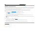
Removing the Front Cover 1. Remove the back cover (see "Removing the Back Cover"). 2. Slide the front cover backward and grasp the cover at both ends (see Figure 5-4). 3. Carefully lift the cover away from the system. Figure 5-4. Removing and Replacing the Front Cover Replacing the Front Cover 1. Check that no tools or parts are left inside the system and that any cables are routed so that they will not be damaged by the cover. 2.
l System error message indicates a keyboard problem Action 1. Look at the keyboard and the keyboard cable for any signs of damage. If the keyboard and its cable appear to be free of physical damage and the keys work, go to step 3. If the keyboard or its cable are damaged, continue to step 2. 2. Swap the faulty keyboard with a working keyboard. If the problem is resolved, the keyboard must be replaced (see "Getting Help" for instructions on obtaining technical assistance). 3.
Troubleshooting a Serial I/O Device Problem l Device connected to the serial port is not working Action 1. Open the front bezel (see "Opening the Bezel"). 2. Turn off the system and any peripheral devices connected to the serial port. 3. Swap the interface cable with a known working cable. If the problem is resolved, the interface cable must be replaced (see "Getting Help" for instructions on obtaining technical assistance). 4.
3. Ensure that the appropriate drivers are installed and the protocols are bound. 4. Enter the System Setup program and confirm that the NICs are enabled (see "Using the System Setup Program" in the User's Guide). 5. Ensure that the NICs, hubs, and switches on the network are all set to the same data transmission speed. 6. Ensure that all network cables are of the proper type and do not exceed the specified length. For more information, see "Network Cable Requirements" in the User's Guide.
l Excessive humidity Action 1. Turn off the system, including any attached peripherals, and disconnect the system from the electrical outlet. 2. Remove the back cover (see "Removing the Back Cover"). 3. Remove the front cover (see "Removing the Front Cover"). 4. Remove all expansion cards installed in the system (see "Removing an Expansion Card" in "Installing System Board Options"). 5. Let the system dry thoroughly for at least 24 hours. 6.
Problem l System caution indicator is amber l Front-panel status LCD indicates a problem with power supply l Power-supply fault indicator signifies a problem Action 1. Locate the faulty power supply. The power supply's fault indicator is lit (see Figure 2-5). NOTICE: The power supplies are hot-pluggable. The system requires two power supplies to be installed for the system to operate normally. Remove and replace only one power supply at a time in a system that is powered on. 2.
Problem l Error message indicates a microprocessor problem l Error message indicates a microprocessor board problem l Front-panel status LCD indicates a problem with microprocessors, VRMs, or the microprocessor board l A heat sink is not installed for each microprocessor NOTICE: If a microprocessor socket does not have a microprocessor installed, a heat sink blank must be installed for that socket. Action 1. Observe the precautions in "Safety First—For You and Your System." 2.
9. Perform the I/O devices tests in the system diagnostics. If the problem persists, see "Getting Help." Troubleshooting the I/O Board Problem l Error message indicating an I/O board problem (expansion-card problem) Action 1. Observe the precautions in "Safety First—For You and Your System." 2. Turn off the system, including any attached peripherals, and disconnect the system from its electrical outlet. 3. Remove the back cover (see "Removing the Back Cover").
Troubleshooting System Memory Problem l Faulty memory module l Faulty memory riser card l Faulty microprocessor board Action 1. Turn on the system, including any attached peripherals. If there are no error messages, go to step 18. 2. Enter the System Setup program to check the system memory setting (see "Using the System Setup Program" in the User's Guide for instructions). 3. If the amount of memory installed in the system matches the system memory setting, go to step 18. 4.
18. Run the system memory test in the system diagnostics. If the test does not complete successfully, see "Getting Help." Troubleshooting the Diskette Drive Problem l Error message indicates a diskette-drive problem Action 1. Enter the System Setup program and verify that the system is configured correctly (see "Using the System Setup Program" in the User's Guide). 2. Open the bezel (see "Opening the Bezel"). 3.
4. Turn off the system, including any attached peripherals, and disconnect the system from its electrical outlet. 5. Ensure that the CD/diskette drive assembly is properly installed (see "Removing the CD/Diskette Drive Tray" in "Installing Drives"). 6. Connect the system to its electrical outlet and turn on the system, including any attached peripherals. 7. Run the IDE devices tests in the system diagnostics to determine whether the CD drive works correctly. If the tests failed, continue to step 8.
l Faulty hard drive l Faulty SCSI backplane board l Faulty or loose SCSI cable connections to a RAID controller card Action NOTICE: This troubleshooting procedure can destroy data stored on the hard drive. Before you proceed, back up all the files on the hard drive. 1. Reboot your system and enter the SCSI configuration utility by pressing , , or , depending on the controller. 2. Check that the primary SCSI channel is enabled, and reboot the system.
Back to Contents Page Installing System Options Dell™ PowerEdge™ 6600 Systems Installation and Troubleshooting Guide Fan Assembly Tray Memory Riser Cards Power Supplies Memory Modules AC Power Module Microprocessor Tray Expansion Cards Microprocessors Peripheral Riser Card System Battery I/O Riser Card This section describes how to install the following options: l Expansion cards l Memory upgrades l Microprocessor upgrades This section also includes instructions for replacing: l Fans l
Removing a Cooling Fan NOTE: The procedure for removing each individual fan is the same. 1. Loosen the thumbscrew that secures the back cover to the chassis (see "Removing the Back Cover" in "Troubleshooting Your System"). 2. Slide the back cover backward to the service position. The back cover service position allows you to remove and replace fans without removing the back cover. NOTICE: The cooling fans are hot-pluggable.
1. Lower the fan into the fan assembly until the fan snaps into position (see Figure 6-2). 2. Rotate the handle down into the installed position. 3. Slide the back cover forward. 4. Tighten the thumbscrew that secures the back cover to the chassis (see "Replacing the Back Cover" in "Troubleshooting Your System"). Power Supplies The system includes three hot-pluggable power supplies. Removing a Power Supply 1.
Replacing the AC Power Module 1. Replace the AC power module by sliding the module into the chassis (see Figure 6-4). 2. Tighten the thumbscrew that secures the AC power module to the chassis. 3. Connect the system to the electrical outlet and turn on the system, including any attached peripherals. Expansion Cards The system includes 11 hot-pluggable expansion slots. Slot 1 operates at 33 MHz. Slots 2 through 11 are capable of operating at 33, 66, or 100 MHz.
If you install expansion cards, you may have some difficulty in directly determining the bus number of a controller on a particular expansion card. However, the PCI bus scan order listed in Table 6-1 can help you determine the relative numbering of PCI buses within the expansion slots. For example, a PCI controller residing in expansion slot 3 will never have a lower bus number than one in slot 2 because slot 2 precedes slot 3 in the scan order. Table 6-1.
5. When the card is seated in the connector, close the expansion-card latch and the card-guide latch (see Figure 6-5). 6. Connect any cables that should be attached to the card. See the documentation that came with the card for information about its cable connections. NOTE: SCSI cables connected from an expansion card to the SCSI backplane board should be routed under the fan assembly tray.
Peripheral Riser Card The peripheral riser card provides the communication signals for the CD/diskette assembly and the control panel. Removing the Peripheral Riser Card 1. Turn off the system, including any attached peripherals, and disconnect the system from the electrical outlet. 2. Remove the back cover (see "Removing the Back Cover" in "Troubleshooting Your System"). 3. Remove the front cover (see "Removing the Front Cover" in "Troubleshooting Your System"). 4.
Removing the I/O Riser Card 1. Turn off the system, including any attached peripherals, and disconnect the system from the electrical outlet. 2. Remove the back cover (see "Removing the Back Cover" in "Troubleshooting Your System"). 3. Disconnect the following I/O riser card cables (see Figure 6-7): l The system status indicator cable l The SCSI cable from the SCSI connector l The chassis intrusion switch cable from the INTR connector Figure 6-7. Removing and Replacing the I/O Riser Card 4.
2. Remove the system front cover (see "Removing the Front Cover" in "Troubleshooting Your System"). 3. Grasp the memory riser card ejectors, and rotate the ejectors up to release the card from the microprocessor board (see Figure 6-8). 4. Lift the memory riser card straight up to clear the chassis. Figure 6-8.
When you install memory modules, follow these guidelines: l Each bank must contain identical modules. You must install memory modules in matched sets of four, two in each memory riser card (see Figure 6-9). l Install identical memory modules in sockets A and B for bank 1 before installing modules in sockets for bank 2, and so on. l Memory banks must be populated sequentially, which means that there can be no empty banks between the first and last populated banks. Figure 6-9.
to make sure that the memory modules are firmly seated in their sockets. 7. Run the system memory test in the system diagnostics. Installing Memory Modules CAUTION: Before you perform this procedure, you must turn off the system and disconnect it from its power source. For more information, see "Safety First—For You and Your System" in "Troubleshooting Your System." NOTICE: See "Protecting Against Electrostatic Discharge" in the safety instructions in your System Information document. 1.
3. Remove the back cover (see "Removing the Back Cover" in "Troubleshooting Your System"). 4. Remove the front cover (see "Removing the Front Cover" in "Troubleshooting Your System"). 5. Raise the following components to the service position: l Memory riser cards (See "Removing the Memory Riser Cards.") l Peripheral riser card (See "Removing the Peripheral Riser Card.") 6. Remove the fan assembly tray (see "Removing the Fan Assembly Tray"). 7.
NOTE: A microprocessor and VRM must be installed in the CPU1 and VRM1 sockets, respectively. To identify CPU1 and VRM1 sockets, see Figure A-4. NOTICE: If a microprocessor socket does not have a microprocessor installed, a heat sink blank must be installed for that socket.
NOTICE: Be careful not to bend any of the pins when removing the microprocessor. Bending the pins can permanently damage the microprocessor. 8. Lift the microprocessor out of the socket and leave the release lever up so that the socket is ready for the new microprocessor (see Figure 6-13). 9. Unpack the new microprocessor. If any of the pins on the microprocessor appear bent, see "Getting Help" for instructions on obtaining technical assistance. 10.
System Setup program and displays the microprocessor ID number, operating speed, processor bus, and cache information. 23. 24. Press to enter the System Setup program, and check that the microprocessor categories match the new system configuration (see "Using the System Setup Program" in your User's Guide). Run the system diagnostics to verify that the new microprocessor is operating correctly.
Back to Contents Page Installing Drives Dell™ PowerEdge™ 6600 Systems Installation and Troubleshooting Guide SCSI Interface Cables SCSI Configuration Information Peripheral Bay External SCSI Tape Drive SCSI Hard Drives CD and Diskette Drives Installing a RAID Controller Card Configuring the Boot Device Your system features a hard-drive bay that contains up to eight 1-inch SCSI hard drives.
4. Slide the tape drive into the peripheral bay. 5. Connect the tape drive's power cable to the power distribution board and to the tape drive. 6. Connect the tape drive's interface cable to the tape drive and to the I/O riser card. 7. Check all cable connections that may have been loosened during this procedure. Arrange the cables so that they will not catch on the system cover or block the airflow of the fans or cooling vents. 8.
NOTICE: Do not insert a hard-drive carrier and attempt to lock its handle next to a partially installed carrier. Doing so can damage the partially installed carrier's shield spring and make it unusable. Ensure that the adjacent drive carrier is fully installed. 4. Insert the hard drive into the drive bay (see Figure 7-1). 5. Close the hard-drive handle to lock it in place. 6. Close the front bezel (see "Closing the Bezel" in "Troubleshooting Your System"). 7.
Figure 7-2. Removing and Replacing the CD/Diskette Drive Tray Installing a RAID Controller Card Follow these general guidelines when installing a RAID controller card. For specific instructions, see the documentation supplied with the controller card. CAUTION: Before you perform this procedure, you must turn off the system and disconnect it from its power source. For more information, see "Safety First—For You and Your System" in "Troubleshooting Your System.
Back to Contents Page Getting Help Dell™ PowerEdge™ 6600 Systems Installation and Troubleshooting Guide Help Overview Dell Contact Numbers Help Overview This section describes the tools Dell provides to help you when you have a problem with your computer. It also tells you when and how to contact Dell for technical or customer assistance. Technical Assistance If you need assistance with a technical problem, perform the following steps: 1. Complete the procedures in "Troubleshooting Your System." 2.
sales@dell.com apmarketing@dell.com (for Asian/Pacific countries only) l Electronic Information Service info@dell.com AutoTech Service Dell's automated technical support service—AutoTech—provides recorded answers to the questions most frequently asked by Dell customers about their portable and desktop computer systems. When you call AutoTech, you use your touch-tone telephone to select the subjects that correspond to your questions. The AutoTech service is available 24 hours a day, seven days a week.
Dell Contact Numbers The following table provides country-specific access codes and telephone numbers, websites, and email addresses that you can use to contact Dell. The codes required depend on where you are calling from as well as the destination of your call; in addition, each country has a different dialing protocol. If you need assistance in determining which codes to use, contact a local or an international operator.
900 Country Code: 43 Home/Small Business Customer Care Preferred Accounts/Corporate Customer Care Home/Small Business Technical Support City Code: 1 Preferred Accounts/Corporate Technical Support Switchboard 01 795 67603 0660 8056 01 795 67604 0660 8779 01 491 04 0 Website: support.euro.dell.com E-mail: tech_support_central_europe@dell.
City Code: 2 Switchboard 02 22 83 27 11 Website: support.euro.dell.com E-mail: czech_dell@dell.com Denmark (Horsholm) International Access Code: 00 Country Code: 45 Technical Support 45170182 Relational Customer Care 45170184 Home/Small Business Customer Care 32875505 Switchboard Fax Technical Support (Upplands Vasby, Sweden) Fax Switchboard 45170100 46 0 859005594 45170117 Website: support.euro.dell.com E-mail: den_support@dell.com E-mail Support for Servers: Nordic_server_support@dell.
Small Business Customer Care 01 204 4026 Country Code: 353 Corporate Customer Care 01 279 5011 City Code: 1 Sales 01 204 4444 SalesFax 01 204 0144 Fax Switchboard 204 5960 01 204 4444 Website: support.euro.dell.com E-mail: dell_direct_support@dell.com Italy (Milan) Home and Small Business Technical Support 02 577 826 90 Customer Care 02 696 821 14 Country Code: 39 Fax 02 696 821 13 City Code: 02 Switchboard 02 696 821 12 International Access Code: 00 Website: support.euro.dell.
Website: support.euro.dell.com E-mail: tech_be@dell.
351 214 220 710 Fax 35 121 424 01 12 E-mail: support.euro.dell.com/es/es/emaildell/ Puerto Rico General Support St.
or 0800 33 555 Thailand Technical Support International Access Code: 001 Customer Service (Penang, Malaysia) Country Code: 66 Sales toll free: 0880 060 07 604 633 4949 toll free: 0880 060 09 Trinidad/Tobago General Support U.K.