
Installation and Troubleshooting Guide

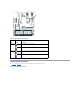
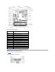
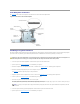
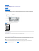
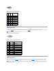
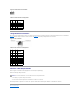

Figure B-4. USB Connector Pin Numbers
Table B-4. USB Connector Pin Assignments
Integrated NIC Connectors
Each of the system's integrated NICs function as a separate network expansion card while providing fast communication between servers and workstations.
FigureB-5 illustrates the pin numbers for the NIC connector and TableB-5 defines the pin assignments for the connectors.
Figure B-5. NIC Connector
Table B-5. NIC Connector Pin Assignments
Network Cable Requirements
The NIC supports a UTP Ethernet cable equipped with a standard RJ45-compatible plug.
Observe the following cabling restrictions.
l Use Category 5 or greater wiring and connectors.
l Do not exceed a cable run length (from a workstation to a hub) of 100 m (328 ft).
For detailed guidelines on operation of a network, see "Systems Considerations of Multi-Segment Networks" in the IEEE 802.3 standard.
Back to Contents Page
Pin
Signal
I/O
Definition
1
Vcc
N/A
Supply voltage
2
DATA
I
Data in
3
+DATA
O
Data out
4
GND
N/A
Signal ground
Pin
Signal
I/O
Definition
1
TD+
O
Data out (+)
2
TD–
O
Data out (–)
3
RD+
I
Data in (+)
4
NC
N/A
No connection
5
NC
N/A
No connection
6
RD–
I
Data in (–)
7
NC
N/A
No connection
8
NC
N/A
No connection
NOTICE: To avoid line interference, voice and data lines must be in separate sheaths.