Dell PowerEdge C5125 Hardware Owner’s Manual Regulatory Model: B04S
Notes, Cautions, and Warnings NOTE: A NOTE indicates important information that helps you make better use of your computer. CAUTION: A CAUTION indicates potential damage to hardware or loss of data if instructions are not followed. WARNING: A WARNING indicates a potential for property damage, personal injury, or death. Information in this publication is subject to change without notice. © 2011 Dell Inc. All rights reserved.
Contents 1 About the System . . . . . . . . . . . . . . . . . . . . . . . . . Front-Panel Features and Indicators 2 . . . . . . . . . . . . . . . . . . Using the System Setup Program . Setup Menu . . . . . . . . . . . . . . . . . . . . . . . . . . . . . . . . . . . . . . . . . . . BIOS Setup Options at Boot . Console Redirection. 7 8 11 11 . . . . . . . . . . . . . . . . . . . . . . 12 . . . . . . . . . . . . . . . . . . . . . . . . . . 12 . . . . . . . . . . . . . . . . . . . . . . . 12 .
3 Installing System Components . . . . . . . . . . . . . . . 47 . . . . . . . . . . . . . . . . . . . . . . . . . 47 . . . . . . . . . . . . . . . . . . . . . . . . . . . 48 Recommended Tools Inside the System Sled Configuration . . . . . . . . . . . . . . . . . . . . . . . . . . . 49 Removing a Sled . . . . . . . . . . . . . . . . . . . . . . . . . . . . 50 Installing a Sled . . . . . . . . . . . . . . . . . . . . . . . . . . . . 50 Removing Memory Modules . . . . . . . . . . . . . . . .
Removing the Chassis Cover . . . . . . . . . . . . . . . . . . . . . . 70 Installing the Chassis Cover . . . . . . . . . . . . . . . . . . . . . . 71 . . . . . . . . . . . . . . . . . . . . . . . . 72 Installing the Fan Cage . . . . . . . . . . . . . . . . . . . . . . . . . 74 Removing a Backplane . . . . . . . . . . . . . . . . . . . . . . . . . 74 Installing a Backplane . . . . . . . . . . . . . . . . . . . . . . . . . 77 Removing the Fan Cage .
6 Getting Help . . . . . . . . . . . . . . . . . . . . . . . . . . . . 97 7 Index . . . . . . . . . . . . . . . . . . . . . . . . . . . . . . . . .
1 About the System The system (C5125) includes the following configurations: • 12-sled, system board+ 3.5" hard-drive board+cables • 12-sled, system board + 2.5" hard-drive board+cables Server management for the C5125 sled is available through a dedicated NIC port at the front of the system. For more information, see "Front-Panel Features and Indicators" on page 8.
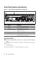
Front-Panel Features and Indicators Figure 1-1. Sled Front Features (Rotated Counter-clockwise 90°) 1 2 2 1 5 Item 4 Feature Description 1 Latch Press to release sled from chassis. 2 Handle Hold to pull sled out of chassis.
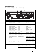
Sled LED Description Figure 1-2.
About the System
Using the System Setup Program 2 Setup Menu The computer employs the latest AMI Core BIOS, which is stored in Flash memory. The Flash memory supports the Plug and Play specification, and contains a BIOS Setup program, the Power On Self Test (POST) routine, and the PCI auto-configuration utility. This system supports system BIOS shadowing which enables the BIOS to execute from 64-bit onboard write-protected DRAM.
BIOS Setup Options at Boot You can initiate SETUP by pressing the respective keys during the POST: Enter the BIOS Setup Console Redirection The console redirection allows a remote user to diagnose and fix problems on a server, which has not successfully booted the operating system (OS). The centerpiece of the console redirection is the BIOS Console. The BIOS Console is a Flash ROM-resident utility that redirects input and output over a serial or modem connection.
For console redirection, an escape sequence starts with an escape character. This character can be entered in a variety of different ways depending on the requirements of your terminal emulation software. For example, 0x1b, ^[, and refer to the same escape character. The following table lists the escape sequence that must be sent to represent a special key or command.
The Legend Bar The legend bar is at the side of the Setup screen. The keys in the legend bar allow you to navigate through the various setup menus. The following table lists the keys found in the legend bar with their corresponding alternates and functions.
Access Level The Access Level property controls who has access to the control (supervisor or user). Table 2-1 summarizes the effect of Access Level on a control. Table 2-1.
Main Menu The Main menu is the screen that is first displayed on entering the BIOS Setup. If an error occurs, the Error Manager screen is displayed. BIOS SETUP UTILITY Main Advanced Boot Server Security System Overview AMIBIOS Version : 1.0.0 Build Date: 01/17/11 Product Information Exit Use [ENTER, [TAB] Or [SHIFT-TAB] to select a Field. Use <-> to configure system time.
AMIBIOS Option Description Version Displays the BIOS version. NOTE: Check this version number when updating BIOS from the manufacturer. Build Date Displays the date the BIOS was created. Product Information Option Description Name System product name. Asset Tag System asset tag number. Service Tag System service tag number. Electronic Piece Part Information from PPID label.
Option Description System Date Scroll to this item to adjust the date. Use [ENTER], [TAB] or [SHIFT-TAB] to select a field. Use [+] or [-] to configure system date.
Advanced Menu The Advanced screen provides an access point to configure several options. On this screen, the user selects the option that is to be configured. Configurations are performed on the selected screen, not directly on the Advanced screen. CAUTION: Making incorrect settings to items on these pages may cause the system to malfunction. Unless you have experience adjusting these items, it is recommended that you leave these settings at the default values.
CPU Configuration Scroll to this item and press to view the following screen: BIOS SETUP UTILITY Advanced CPU Configuration Enable/Disable Module Version :13.65 Secure Virtual Machine AGESA Version :3.5.5.0 Mode (SVM) Physical Count :1 Logical Count :4 AMD Phenom II Processor 910e Revision :C2 Cache L1 :512KB Cache L2 :2048KB Cache L3 :6MB Speed: :2500MHz Able to Change Freq.
Options: • Module Version : CPU module version. • AGESA Version : AMD Generic Encapsulated Software Architecture (AGESA) version number. • Physical Count : Number of physical CPUs. • Logical Count : Number of logical CPUs. • Revision : Processor revision • Cache L1: Information only. Displays the size of CPU L1. • Cache L2: Information only. Displays the size of CPU L2. • Cache L3: Information only. Displays the size of CPU L3.
SATA Configuration Scroll to this item and press to view the following screen: BIOS SETUP UTILITY Advanced SATA Configuration OnChip SATA Type Options [Native IDE]*1 Native IDE AHCI • SATA Port0 [Hard Disk] • SATA Port1 [Not Detected] • SATA Port2 [Not Detected] • SATA Port3 [Not Detected] Power Saving Features [Disabled]*2 , Enter F1 F10 ESC Select Screen Select Item Go to Sub Screen General Help Save and Exit Exit *1: [Native IDE] [AHCI] *2: [Enable] [Disabled].
SATA Port0-3: [Not Detected][Hard Disk][ATAPI CDROM] While entering setup, BIOS auto detects the presence of SATA devices. This displays the status of auto detection of SATA devices. This item displays information only and is unavailable when AHCI Mode is enabled. Power Saving Features: Disable/Enable power saving features in the server board.
*2: [Disabled] [Enabled with PXE] [Enabled without PXE] *3: [Disabled] [Enabled with PXE] [Enabled without PXE] NIC1 - Intel 82576EB: [Disabled][Enabled with PXE][Enabled without PXE] NIC2 - Intel 82576EB: [Disabled][Enabled with PXE][Enabled without PXE] Control Group User Access Level iSCSI Remote Boot Access Level 1 NIC1 – 82576EB Access Level 1 NIC1 – 82576EB Access Level 1 IOMMU Access Level 1 24 Using the System Setup Program
Active State Power Management Configuration Scroll to this item and press to view the following screen: BIOS SETUP UTILITY Advanced Active State Power Management Configuration Active State Power Management (ASPM).
USB Configuration Scroll to this item and press to view the following screen: BIOS SETUP UTILITY Advanced USB Configuration Enables support for legacy USB. AUTO option disables legacy support if no USB devices are connected. Module Version - 2.24.5-13.
Legacy USB Support: Control Group User Access Level Legacy USB Support Access Level 1 USB PORT 0(Front 0) Access Level 1 USB PORT 1(Front 1) Access Level 1 USB PORT 2(BMC) Access Level 1 USB PORT 3(SSD) Access Level 1 Using the System Setup Program 27
Boot Menu This page enables you to set POST boot parameters. Scroll to this item and press to view the following screen: BIOS SETUP UTILITY Boot Boot Settings Configure Settings during System Boots.
Boot Settings Configuration Select this item and press Enter to view the following submenu items: BIOS SETUP UTILITY Boot Boot Settings Configuration Quick Boot [Enabled] Quiet Boot [Enabled] Wait For ’F1’ If Error [Disabled] Force PXE First [Enabled] *1 Force PXE First Boot Only [Disabled] Force USB First [Disabled] Allows BIOS to skip certain tests while booting. This will decrease the time needed to boot the system.
Force USB First: Enable/Disable USB to be the first boot device, the priority is higher than PXE.
Boot Device Priority Select this item and press to view the following submenu items: BIOS SETUP UTILITY Boot Boot Device Priority 1st Boot Device [Network:IBA GB Slo] Specifies the boot sequence from the available devices A device enclosed in parenthesis has been disabled in the corresponding type menu.
Control Group User Access Level 6th Boot Device Access Level 1 7th Boot Device Access Level 1 8th Boot Device Access Level 1 9th Boot Device Access Level 1 10th Boot Device Access Level 1 11th Boot Device Access Level 1 12th Boot Device Access Level 1 32 Using the System Setup Program
Server Menu The Server Management screen provides fields to configure several server management features. It also provides an access point to the screens for configuring console redirection and displaying system information. Scroll to this item and press to view the following screen: BIOS SETUP UTILITY Main Advanced Boot Server Security Exit IPMI Information Status Of BMC Working IPMI Specification Version 2.
BMC Firmware Version: Information only. Displays the Firmware version of BMC. NIC1 Mac Address: [xx-xx-xx-xx-xx-xx] Information only. Displays the NIC1 MAC address. NIC2 Mac Address: [xx-xx-xx-xx-xx-xx] Information only. Displays the NIC2 MAC address. Set BMC LAN Configuration: Input for Set LAN Configuration command. Remote Access Configuration: Configure Remote Access.
BMC LAN Configuration The BMC LAN Configuration screen provides a way to configure BMC LAN setting.
Subnet Mask [xxx.xxx.xxx.xxx]: Enter a Subnet Mask in decimal in the form of XXX.XXX.XXX.XXX (XXX less than 256 and in decimal only). Gateway Address [xxx.xxx.xxx.xxx]: Enter Gateway Address in decimal in the form of XXX.XXX.XXX.XXX (XXX less than 256 and in decimal only). MAC Address: Displays the MAC address.
*2: [115200 8,n,1][57600 8,n,1][38400 8,n,1][19200 8,n,1][9600 8,n,1] *3: [None] [Hardware] [Software] *4: [ANSI] [VT100] [VT-UTF8] *5: [Disabled] [Always] Remote Access: [Disabled][Enabled] Select Remote Access type. Serial port number: [COM1][COM2] Select Serial Port for console redirection. Current SOL Baud Rate: Information only. Displays the current SOL Baud Rate. Serial Port Mode: [115200 8,n,1][57600 8,n,1][38400 8,n,1][19200 8,n,1][9600 8,n,1]Select Serial Port settings.
View BMC Event Log Select View BMC Event Log to view the following submenu: BIOS SETUP UTILITY Server Total Number of Entries 2 SEL Entry Number [1] SEL Record ID: 0001 SEL Record Type: 02 (System Event) Event Timestamp: Unspecified Generator ID: 0001 Event Message Format Ver: 04 (IPMI ver 2.
Security Menu The Security screen provides fields to enable and set the user and administrative password and to lockout the front panel buttons so they cannot be used. Scroll to this item and press to view the following screen: BIOS SETUP UTILITY Security Security Settings Supervisor Password Not Installed User Password Not Installed Install or change the password.
Select this option and press to access the sub menu, a dialog box appears which lets you enter a password. You can enter no more than six letters or numbers. Press Enter after you have typed in the password. A second dialog box asks you to retype the password for confirmation. Press Enter after you have retyped it correctly. If the password confirmation is incorrect, an error message appears. The password is stored in NVRAM after ezPORT completes.
Save Changes and Exit: Highlight this item and press Enter to save any changes that you have made in the Setup utility and exit the Setup utility. When the Save Changes and Exit dialog box appears, press to save the changes and exit, or press to return to the setup main menu. Discard Changes and Exit: Highlight this item and press to discard any changes that you have made in the Setup utility and exit the Setup utility.
Loading BIOS Defaults Different mechanisms exist for resetting the system configuration to the default values. When a request to reset the system configuration is detected, the BIOS loads the default system configuration values during the next POST. The request to reset the system to the defaults can be sent in the following ways: • A request to reset the system configuration can be generated by pressing from within the BIOS Setup utility.
POST Error Messages and Handling: Code Error Message Response 0000 Timer Error Pause 0003 CMOS Battery Low Pause 0004 CMOS Settings Wrong Pause 0005 CMOS Checksum Bad Pause 000B CMOS memory size Wrong Pause 000C RAM R/W test failed Pause 000E A: Driver Error Pause 000F B: Driver Error Pause 0012 CMOS Date/Time Not Set Pause 0040 Refresh timer test failed Halt 0041 Display memory test failed Pause 0042 CMOS Display Type Wrong Pause 0044 DMA Controller Error Halt 0045
0082 Secondary Master Drive – ATAPI Incompatible Pause 0083 Secondary Slave Drive – ATAPI Incompatible Pause 0160 The processors installed in your system are not able to match their frequencies. Pause 0162 The processors installed in your system do not have the same cache size. Halt 0163 The processor(s) installed in your system are not known by the BIOS. Please contact your BIOS vendor for appropriate updates.
8101 Warning! USB Host Controller not found at the specified address!!! WARNING 8102 Error! USB device failed to initialize!!! WARNING 8103 Warning! Unsupported UBS device found and disabled!!! WARNING 8104 Warning! Port 60h/64h emulation is not supported by this USB Host Controller!!! WARNING 8105 Warning! EHCI controller disabled. It requires 64-bit data support in the BIOS. Pause 8400 Warning!! Insufficient memory! Remote access is disabled.
Using the System Setup Program
Installing System Components 3 Recommended Tools • Phillips screwdriver • Flat-tipped screwdriver • Set of jewellers screwdrivers • A grounding strap • An anti-static pad Installing System Components 47
Inside the System CAUTION: Many repairs may only be done by a certified service technician. You should only perform troubleshooting and simple repairs as authorized in your product documentation, or as directed by the online or telephone service and support team. Damage due to servicing that is not authorized is not covered by warranty. Read and follow the safety instructions that came with the product. CAUTION: This system must be operated with the system cover installed to make sure of proper cooling.
Sled Configuration Figure 3-2 shows the 12-sled configuration with the corresponding bay numbering. Figure 3-2.
Removing a Sled CAUTION: To ensure proper airflow in the system, if a sled is removed it should be immediately replaced with another sled or sled dummy. CAUTION: Many repairs may only be done by a certified service technician. You should only perform troubleshooting and simple repairs as authorized in your product documentation, or as directed by the online or telephone service and support team. Damage due to servicing that is not authorized is not covered by warranty.
Removing Memory Modules WARNING: The memory modules are hot to touch for some time after the system has been powered down. Allow time for the memory modules to cool before handling them. Handle the memory modules by the card edges and avoid touching the components on the memory module. CAUTION: Many repairs may only be done by a certified service technician.
Installing a Memory Module WARNING: The memory modules are hot to touch for some time after the system has been powered down. Allow time for the memory modules to cool before handling them. Handle the memory modules by the card edges and avoid touching the components on the memory module. CAUTION: Many repairs may only be done by a certified service technician.
Supported DIMM Configuration The following DIMM configurations are supported by the C5125 system. Figure 3-5. DIMM slot configuration DIMM_A0 DIMM_B0 DIMM_A1 B1 A1 B0 A0 DIMM_B1 DIMM Population Rules For one DIMM, only install in DIMM A1/B1. For two DIMMs, install in DIMM A1 + B1. DDR Rate 1.5V DDR Rate 1.
DDR Rate 1.5V DDR Rate 1.
Supported Memory Supported Memory Configuration Memory Type/Size CPU DIMMs Type Memory Speed (MHz) Rank Type Component Total (x8, x4) Density Size DIMM Slot A0 B0 A1 B1 12-sled DDR3 ECC UDIMM/2048MB*1 1 1 VLP 1333 UDIMM MHz 2R x8 1 Gb 2G • 12-sled DDR3 ECC UDIMM/2048MB*2 1 2 VLP 1333 UDIMM MHz 2R x8 1 Gb 4G • • 12-sled DDR3 ECC UDIMM/2048MB*3 1 3 VLP 1333 UDIMM MHz 2R x8 1 Gb 6G • • • 12-sled DDR3 ECC 1 UDIMM/4096MB*1+ 2048MB*2 3 VLP 1333 UDIMM MHz 2R x8 2 Gb/
Removing 2.5" Hard-Drives CAUTION: Many repairs may only be done by a certified service technician. You should only perform troubleshooting and simple repairs as authorized in your product documentation, or as directed by the online or telephone service and support team. Damage due to servicing that is not authorized is not covered by warranty. Read and follow the safety instructions that came with the product. 1 Remove the sled from the system. See "Removing a Sled" on page 50.
4 Remove the four screws of the 2.5" hard-drive bracket, then detach the hard-drive from the bracket. See Figure 3-8. Figure 3-8. Removing and Installing the 2.5" Hard-Drive Bracket NOTE: The correct orientation of the bracket with the arrow mark pointing towards the hard-drive connector. Installing 2.5" Hard-Drives CAUTION: Many repairs may only be done by a certified service technician.
Removing 3.5" Hard-Drives CAUTION: Many repairs may only be done by a certified service technician. You should only perform troubleshooting and simple repairs as authorized in your product documentation, or as directed by the online or telephone service and support team. Damage due to servicing that is not authorized is not covered by warranty. Read and follow the safety instructions that came with the product. 1 Remove the sled from the system. See "Removing a Sled" on page 50.
Figure 3-10. Removing and Installing the 3.5" Hard-Drives From the Sled 3.5” HDD HDD0 1 2 HDD0 HDD0 SATA0 HDD1 SATA1 3.5” HDD HDD1 1 3 HDD1 1 4 1 cable clip 2 hard-drive 0 power connector 3 hard-drive 1 power connector 4 hard-drive SATA connectors 5 Disconnect the hard-drive cables from the hard-drive. See Figure 3-11. Figure 3-11. Removing and Installing the 3.
Installing 3.5" Hard-Drives CAUTION: Many repairs may only be done by a certified service technician. You should only perform troubleshooting and simple repairs as authorized in your product documentation, or as directed by the online or telephone service and support team. Damage due to servicing that is not authorized is not covered by warranty. Read and follow the safety instructions that came with the product. 1 Connect the hard-drive cables to a new hard-drive. See Figure 3-11.
Figure 3-12. Removing and Installing the Heat Sink Installing a Heat Sink CAUTION: Many repairs may only be done by a certified service technician. You should only perform troubleshooting and simple repairs as authorized in your product documentation, or as directed by the online or telephone service and support team. Damage due to servicing that is not authorized is not covered by warranty. Read and follow the safety instructions that came with the product.
Removing a Processor CAUTION: Many repairs may only be done by a certified service technician. You should only perform troubleshooting and simple repairs as authorized in your product documentation, or as directed by the online or telephone service and support team. Damage due to servicing that is not authorized is not covered by warranty. Read and follow the safety instructions that came with the product. 1 Remove the heat sink. See "Removing a Heat Sink" on page 60.
Installing a Processor CAUTION: Positioning the processor incorrectly can permanently damage the system board or the processor. Be careful not to bend the pins in the socket. Do not use force to seat the processor. CAUTION: Many repairs may only be done by a certified service technician. You should only perform troubleshooting and simple repairs as authorized in your product documentation, or as directed by the online or telephone service and support team.
4 Disconnect the hard-drive board from the system board and lift out of the sled. See Figure 3-15. Figure 3-15. Removing and Installing the 2.5" Hard-Drive Board 1 Installing the 2.5" Hard-Drive Board CAUTION: Many repairs may only be done by a certified service technician. You should only perform troubleshooting and simple repairs as authorized in your product documentation, or as directed by the online or telephone service and support team.
Removing the 3.5" Hard-Drive Board CAUTION: Many repairs may only be done by a certified service technician. You should only perform troubleshooting and simple repairs as authorized in your product documentation, or as directed by the online or telephone service and support team. Damage due to servicing that is not authorized is not covered by warranty. Read and follow the safety instructions that came with the product. 1 Remove the hard-drives. See "Removing 3.5" Hard-Drives" on page 58.
Installing the 3.5" Hard-Drive Board CAUTION: Many repairs may only be done by a certified service technician. You should only perform troubleshooting and simple repairs as authorized in your product documentation, or as directed by the online or telephone service and support team. Damage due to servicing that is not authorized is not covered by warranty. Read and follow the safety instructions that came with the product. 1 Place the hard-drive board into the sled and connect to the system board.
Removing the System Board CAUTION: Many repairs may only be done by a certified service technician. You should only perform troubleshooting and simple repairs as authorized in your product documentation, or as directed by the online or telephone service and support team. Damage due to servicing that is not authorized is not covered by warranty. Read and follow the safety instructions that came with the product. 1 Remove the hard-drive board. See "Removing the 2.
Removing a Power Supply Unit CAUTION: Many repairs may only be done by a certified service technician. You should only perform troubleshooting and simple repairs as authorized in your product documentation, or as directed by the online or telephone service and support team. Damage due to servicing that is not authorized is not covered by warranty. Read and follow the safety instructions that came with the product. 1 Unplug the power cable from the power supply unit. See Figure 3-18.
Installing a Power Supply Unit CAUTION: Many repairs may only be done by a certified service technician. You should only perform troubleshooting and simple repairs as authorized in your product documentation, or as directed by the online or telephone service and support team. Damage due to servicing that is not authorized is not covered by warranty. Read and follow the safety instructions that came with the product.
Removing the Chassis Cover WARNING: Do not attempt to lift the system by yourself. To avoid injury always obtain assistance from others. CAUTION: Make sure all power is disconnected from the system before proceeding. CAUTION: The system must be operated with the system cover installed to ensure proper cooling. CAUTION: Many repairs may only be done by a certified service technician.
Installing the Chassis Cover CAUTION: Many repairs may only be done by a certified service technician. You should only perform troubleshooting and simple repairs as authorized in your product documentation, or as directed by the online or telephone service and support team. Damage due to servicing that is not authorized is not covered by warranty. Read and follow the safety instructions that came with the product. CAUTION: Do not attempt to lift the system by yourself.
Removing the Fan Cage CAUTION: Many repairs may only be done by a certified service technician. You should only perform troubleshooting and simple repairs as authorized in your product documentation, or as directed by the online or telephone service and support team. Damage due to servicing that is not authorized is not covered by warranty. Read and follow the safety instructions that came with the product. 1 Remove the chassis cover. See "Removing the Chassis Cover" on page 70.
4 Disconnect all system and PSU fan cables from the backplane and remove the system fan cables from the cable clips. See Figure 3-22. Figure 3-22. Disconnecting and Connecting the Fan Cables 1 4 2 5 3 6 7 1 fan and connector 1 2 fan and connector 2 3 fan and connector 3 4 fan and connector 4 5 fan and connector 5 6 fan and connector 6 7 fan and connector 7 8 fan and connector 8 8 9 Remove the fan cage completely from the system.
Installing the Fan Cage CAUTION: Many repairs may only be done by a certified service technician. You should only perform troubleshooting and simple repairs as authorized in your product documentation, or as directed by the online or telephone service and support team. Damage due to servicing that is not authorized is not covered by warranty. Read and follow the safety instructions that came with the product.
Figure 3-23. Removing and Installing the Backplane Cables 1 2 3 4 5 6 1 LAN connector 2 sideband connector 3 PMBus 2 connector 4 PMBus 1connector 5 PSU 1 connector 6 PSU 2 connector 7 Remove the two screws behind the power cord bracket attaching the grounding cables to the chassis. See Figure 3-24. Figure 3-24.
8 Remove the two screws from the sides of the power cord bracket. See Figure 3-25. 9 Remove the power cord bracket. See Figure 3-25. Figure 3-25. Removing and Installing the Power Cord Bracket 10 Remove the thirteen screws from the backplane. See Figure 3-26. 11 Remove the backplane from the chassis. See Figure 3-26. Figure 3-26.
Installing a Backplane CAUTION: Many repairs may only be done by a certified service technician. You should only perform troubleshooting and simple repairs as authorized in your product documentation, or as directed by the online or telephone service and support team. Damage due to servicing that is not authorized is not covered by warranty. Read and follow the safety instructions that came with the product. 1 Replace the backplane on the chassis. See Figure 3-26.
4 Guide the PSU1 and the PSU2 power cables through the opening in the middle wall on the chassis. See Figure 3-27. 5 Remove the three screws from the Power Distribution Board (PDB) bracket. See Figure 3-27. 6 Lift the PDB assembly clear from the chassis. Figure 3-27. Removing and Installing the Cables and PDB Bracket 1 2 1 LAN and sideband cable clips 3 power and PMBus cable clips 3 2 middle wall opening 7 Disconnect the PSU power cable from the PDB connector. See Figure 3-28.
Figure 3-28. Removing and Installing the PDB Cables and PDB 1 2 6 3 4 5 1 PDB 2 2 PMBus cable 2 3 PSU 2 power cable 4 PMBus cable 1 5 PSU 1 power cable 6 PDB 1 Installing a PDB Board CAUTION: Many repairs may only be done by a certified service technician. You should only perform troubleshooting and simple repairs as authorized in your product documentation, or as directed by the online or telephone service and support team.
8 Secure the power cables and PMBus cables with the two cable clips on the chassis. See Figure 3-27. 9 Secure the LAN cable and sideband cable with three cable clips. See Figure 3-27. 10 Replace the backplane. See "Installing a Backplane" on page 77. Removing the RTC Battery CAUTION: Many repairs may only be done by a certified service technician.
Installing the RTC Battery CAUTION: Many repairs may only be done by a certified service technician. You should only perform troubleshooting and simple repairs as authorized in your product documentation, or as directed by the online or telephone service and support team. Damage due to servicing that is not authorized is not covered by warranty. Read and follow the safety instructions that came with the product. 1 Install the RTC battery on the system board. See Figure 3-29.
Installing System Components
4 Troubleshooting Troubleshooting Sequence Server Boot Issues System Does Not Boot After Initial Installation Power Connector Not Plugged In Monitor Issues Power Supply and Chassis Issues Cable Issues Electrical Short or Overload Defective Components System Does Not Boot After Configuration Changes Hardware Changes Software Changes BIOS Changes Viewing System Event Logs For Investigation Installation Problems Troubleshooting External Connections System Does Not Boot After Initial Installation Power Connec
Memory Issues If you have installed incompatible memory modules, the system may not boot. Verify the memory you've installed has been tested with your board. If the installed memory is compatible, remove and reinstall the memory modules. Defective memory modules may cause boot errors. To isolate a specific memory module as defective, boot the system with just one memory module installed at a time. Monitor Issues Monitor configurations can cause boot failure.
• If the PDU or the AC outlet has an on/off switch, make sure that it is on and verify that the outlet is supplying current. • Check for foreign objects inside the chassis such as screws that can short circuit connections. Cable Issues Ensure that all cable connections, both internal and external, are attached correctly and securely. Electrical Short or Overload Remove non-essential items such as extra controller cards or IDE/ATAPI devices to check for shorts and over-loads.
Software Changes If you recently installed new software or new device drivers: Try booting into Safe Mode and uninstall the new software or driver. If you can now boot normally, there may be a compatibility issue between the new software or driver and some component in your system. Contact the software manufacturer for assistance. BIOS Changes Changes to some advanced BIOS settings (such as those found in the "Advanced Menu" on page 19) can cause boot issues.
Installation Problems Perform the following checks if you are troubleshooting an installation problem: • Check all cable and power connections (including all rack cable connections). • Unplug the power cord, and wait one minute. Then reconnect the power cord and try again. • If the network is reporting an error, see if there is enough memory installed and disk space available. • Remove all added options, one at a time, and try to power up the system.
Troubleshooting
5 Jumpers and Connectors C5125 System Board Components Figure 5-1 displays the system components on the system board. Figure 5-1.
1 VGA/USB port 2 NIC1 and NIC2 3 processor socket 4 BMC disable jumper 5 BMC COM port 6 IPMB connector 7 JP11 COM port jumper 8 JP12 COM port jumper 9 COM port 10 SSD header 11 SATA connectors 12 PCIe (Sideband) x1 13 hard-drive active LED connector 14 power connector 15 CMOS clear jumper 16 DIMM slots 17 power button connector Jumper Description Default Setting Function JP1 CMOS clear jumper 1-2 1-2 Hold 2-3 Clear JP2 BMC disable jumper Short Open: BMC disable J
2.5" Hard-Drive Board Connectors Figure 5-2 shows the connectors on the 2.5" hard-drive board. Figure 5-2. 2.
3.5" Hard-Drive Board Connectors Figure 5-3 shows connectors on the 3.5" hard-drive board. Figure 5-3. 3.5" Hard-Drive Board 5 2 1 4 3 1 backplane connector 2 hard-drive 0 power connector 3 hard-drive 1 power connector 4 system board gold finger 5 hard-drive LED connector Backplane Connectors 12-Sled Backplane Front Connectors Figure 5-4 shows the 12-sled backplane front connectors. Figure 5-4.
1 sled 1 connector 2 sled 2 connector 3 sled 3 connector 4 sled 4 connector 5 sled 5 connector 6 sled 6 connector 7 sled 7 connector 8 sled 8 connector 9 sled 9 connector 10 sled 10 connector 11 sled 11 connector 12 sled 12 connector 12-Sled Backplane Rear Connectors Figure 5-5 shows the connectors on the rear of the backplane. Figure 5-5.
Table 5-2. 12-Sled Backplane Jumper Positions MD2 MD1 Mode 0 1 Normal 1 1 JTAG 1 0 Boot Power Distribution Board Connectors Figure 5-6 shows the connectors on the PDB. Figure 5-6. PDB Connectors 1 1 2 PSU connector 2 PMBus connector PDB Power and PMBus Connectors This section provides information for the PDB power and SMBus connector pin out. Table 5-3.
Table 5-3.
Jumpers and Connectors
6 Getting Help Contacting Dell For customers in the United States, call 800-WWW-DELL (800-999-3355). NOTE: If you do not have an active Internet connection, you can find contact information on your purchase invoice, packing slip, bill, or Dell product catalog. Dell provides several online and telephone-based support and service options. Availability varies by country and product, and some services may not be available in your area.
Getting Help
7 Index A about the system 7 access level 15 C connector system board 89 contacting dell 97 D Dell contacting 97 DIMM configuration 53 population rules 53 I installing 2.5" hard-drive board 64 3.5" harddrive board 66 backplane 77 chassis cover 71 fan cage 74 memory module 52 PDB Board 79 power supply unit 69 RTC Battery 81 sled 50 system board 67 IRQ assignment conflicts 45 M memory supported 55 menu advanced 19 boot 28 exit 40 main 16 security 39 server 33 R removing 2.5" hard-drive board 63 3.
sled configuration 49 front features 8 LED description 9 population rules 8 special keys configuring 12 system configurations 7 inside 48 setup program 11 T tools recommended 47 troubleshooting sequence 83 100