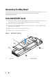
Dell PowerEdge C8220X Tesla K20 GPGPU Card Installation Guide Regulatory Model: B06B Regulatory Type: B06B001
Notes, Cautions, and Warnings NOTE: A NOTE indicates important information that helps you make better use of your computer. CAUTION: A CAUTION indicates potential damage to hardware or loss of data if instructions are not followed. WARNING: A WARNING indicates a potential for property damage, personal injury, or death. ____________________ Information in this publication is subject to change without notice. © 2013 Dell Inc. All rights reserved.
Contents Important Safety Information . Recommended Tools . . . . . . . . . . . . . . . . . . . . 5 . . . . . . . . . . . . . . . . . . . . . . . . . 5 Information You May Need . Tesla K20 GPGPU Cards . . . . . . . . . . . . . . . . . . . . . 6 . . . . . . . . . . . . . . . . . . . . . . . 6 7 Installing the Front Tesla K20 GPGPU card . . . . . . . . Installing the Back Tesla K20 GPGPU card . . . . . . . 10 . . . . . . . . . . . . . . . . . . . . . . 15 Cable Routing Diagram .
Contents
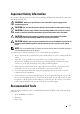
Important Safety Information Observe the following safety precautions when installing NVIDIA Tesla K20 GPGPU cards in the PowerEdge C8220X sled. WARNING: Working on systems that are still connected to a power supply can be extremely dangerous. CAUTION: The sled must be operated with the cover installed to ensure proper cooling. CAUTION: To ensure proper airflow in the PowerEdge C8000 server enclosure, if a sled module is removed it should be immediately replaced with another sled or sled blank.
Information You May Need For information about system features, troubleshooting, and component replacement, see the PowerEdge C8220X Hardware Owner’s Manual. This document is available at support.dell.com/manuals. Tesla K20 GPGPU Cards 1 Remove the sled from the PowerEdge C8000 server enclosure. For detailed information on removing the sled, see the PowerEdge C8220X Hardware Owner’s Manual. 2 Place the sled on a flat, stable surface. 3 Open the sled.
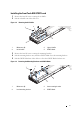
Installing the Front Tesla K20 GPGPU card 1 Remove the four M3 screws securing the air baffles. 2 Lift the air baffles out of the sled cover. Figure 1-2. Removing the Air Baffles 2 1 3 4 1 M3 screws (4) 2 right air baffle 3 left air baffle 4 GPGPU blank 3 Remove the four M3 screws securing the mounting brackets. 4 Lift the mounting brackets away from the GPGPU blank. Save the mounting brackets. 5 Lift the GPGPU blank out of the sled cover. Save the GPGPU blank for future use. Figure 1-3.
6 Align the right air baffle with the screw holes on the front of the sled cover. 7 Secure the right air baffle to the sled cover using the two M3 screws. Tighten the screws to 5.21 in-lbs. Figure 1-4. Installing the Right Air Baffle 2 1 1 M3 screws (2) 2 right air baffle 8 Align the front mounting bracket with the screw holes on the left of the GPGPU card and secure with two M3 screws. Tighten the screws to 5.21 in-lbs.
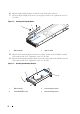
10 Connect the power cables to the GPGPU card. Ensure the cables are properly attached. 11 Connect the emergency throttling cable to the GPGPU card. See Figure 1-17 for the cable routing diagram. Figure 1-6. Connecting the Power and Emergency Throttling Cables 1 2 3 1, 2 power cables 3 emergency throttling cable 12 Align and insert the GPGPU card assembly into the front GPGPU card riser connector until the card is fully seated.
14 Align the left air baffle with the screw holes on the front of the sled cover. 15 Secure the left air baffle to the sled cover using the two M3 screws. Tighten the screws to 5.21 in-lbs. Figure 1-8. Installing the Left Air Baffle 2 1 3 1 left air baffle 3 Tesla K20 GPGPU card assembly 2 M3 screws (2) Installing the Back Tesla K20 GPGPU card 1 Release the cables from the retaining clips and slightly lift the cables to access the screws on the sled cover. Figure 1-9.
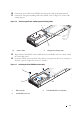
2 Remove the four M3 screws securing the air baffles. 3 Lift the air baffles out of the sled cover. Figure 1-10. Removing the Air Baffles 2 1 3 4 1 M3 screws (4) 2 right air baffle 3 left air baffle 4 GPGPU blank 4 Remove the four M3 screws securing the mounting brackets. 5 Lift the mounting brackets away from the GPGPU blank. Save the mounting brackets. 6 Lift the GPGPU blank out of the sled cover. Save the GPGPU blank for future use. Figure 1-11.
7 Align the right air baffle with the screw holes on the back of the sled cover. 8 Secure the right air baffle to the sled cover using the two M3 screws. Tighten the screws to 5.21 in-lb. Figure 1-12. Installing the Right Air Baffle 1 1 2 M3 screws (2) 2 right air baffle 9 Align the front mounting bracket with the screw holes on the left of the GPGPU card and secure with two M3 screws. Tighten the screws to 5.21 in-lb.
11 Connect the power cables to the GPGPU card. Ensure the cables are properly attached. 12 Connect the emergency throttling cable to the GPGPU card. Figure 1-14. Connecting the Power and Emergency Throttling Cables 1 2 3 1, 2 power cables 3 emergency throttling cable 13 Align and insert the GPGPU card assembly into the back GPGPU card riser connector until the card is fully seated. 14 Secure the GPGPU card to the back of the sled cover using the four M3 screws, working in a clockwise sequence.
15 Align the left air baffle with the screw holes on the back of the sled cover. 16 Secure the left air baffle to the sled cover using the two M3 screws. Tighten the screws to 5.21 in-lb. 17 Route the cables along the inside wall of the sled cover. 18 Secure the cables to the retaining clips. Figure 1-16. Installing the Left Air Baffle 2 1 3 4 1 left air baffle 2 M3 screws (2) 3 power and emergency throttling cables 4 retaining clips (3) 19 Replace the top cover. 20 Close the sled.
Cable Routing Diagram NOTE: Route the cables properly inside the sled to prevent the cables from being pinched or crimped. Figure 1-17.
1 power connector on front GPGPU card riser 2 power connector on back GPGPU card riser 3 twin axial cable on back GPGPU card riser 4 twin axial cable connector on system board 5 power/emergency throttling connector on node power distribution board (NPDB) 6 power/emergency throttling connector on NPDB 7 power connector on NPDB 8 power connector on NPDB 9 power connector on NPDB 10 power connector on NPDB 11 power connector on NPDB 12 power connector on back Tesla K20 GPGPU card 13