Dell PowerEdge FC630 Owner's Manual Regulatory Model: E02B Regulatory Type: E02B004 October 2020 Rev.
Notes, cautions, and warnings NOTE: A NOTE indicates important information that helps you make better use of your computer. CAUTION: A CAUTION indicates either potential damage to hardware or loss of data and tells you how to avoid the problem. WARNING: A WARNING indicates a potential for property damage, personal injury, or death. © 2016 Dell Inc. All rights reserved. This product is protected by U.S. and international copyright and intellectual property laws.
Contents Chapter 1: Dell PowerEdge FC630 overview .................................................................................. 7 Supported configurations for the PowerEdge FC630 system..................................................................................7 Front panel............................................................................................................................................................................ 8 2.5-inch hard drive or SSD system...................
System Setup..................................................................................................................................................................... 25 Viewing System Setup............................................................................................................................................... 26 System Setup details................................................................................................................................................
Processors.......................................................................................................................................................................... 80 Removing a heat sink................................................................................................................................................. 80 Removing a processor...........................................................................................................................................
Chapter 9: Troubleshooting your system....................................................................................122 Troubleshooting system memory.................................................................................................................................122 Troubleshooting hard drives..........................................................................................................................................123 Troubleshooting USB devices............................
1 Dell PowerEdge FC630 overview The Dell PowerEdge FC630 is a half-height sled supported on the PowerEdge FX2 enclosure and support up to: ● ● ● ● ● ● One or two Intel Xeon E5-2600 v3 or E5-2600 v4 processors 24 DIMMs Single processor: Up to two 2.5-inch hard drives Single processor: Up to eight 1.8-inch SSDs Dual processor: Up to two 2.5-inch hard drives Dual processor: Up to eight 1.
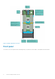
Figure 1. FC630 configuration overview Front panel The features on the front panel include USB management port, iDRAC Direct LED indicator, sled handle and status indicator.
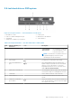
2.5-inch hard drive or SSD system Figure 2. Front panel features — 2.5-inch hard drive or SSD system 1. 3. 5. 7. Hard drives or SSDs USB 2.0 or iDRAC managed USB port Sled handle Sled power-on indicator, power button 2. USB 3.0 port 4. iDRAC Direct LED indicator 6. Status indicator Table 1. Front panel features — 2.5-inch hard drive or SSD system Item Indicator, Button, or Connector 1 Hard drives or SSDs Icon Description 2.5-inch hard drive system Two 2.
1.8-inch SSD system Figure 3. Front panel features — 1.8-inch SSD system 1. 3. 5. 7. SSDs USB 2.0 port or iDRAC Direct port Sled handle Sled power-on indicator, power button 2. USB 3.0 port 4. iDRAC Direct LED indicator 6. Status indicator Table 2. Front panel features — 1.8-inch SSD system Item Indicator, Button, or Connector 1 SSDs Icon Description 1.8-inch SSD system Eight 1.8-inch hot-swap SATA SSDs.
Diagnostic Indicators The diagnostic indicators on the system front panel display error status during system startup. iDRAC Direct LED indicator codes NOTE: The iDRAC Direct LED indicator does not turn on for the USB mode. Figure 4. iDRAC Direct LED indicator 1. iDRAC Direct status indicator Table 3. iDRAC Direct LED indicators Convention iDRAC Direct LED indicator pattern Condition A Green Turns green for a minimum of two seconds at the starting and end of a file transfer.
2. restart the system 3. enter the System Setup 4. set the drive as first in the boot sequence The USB device is displayed in the boot order setup screen only if it is attached to the system before you run the System Setup. You can also select the boot device by pressing F11 during system start-up and selecting a boot device for the current boot sequence.
Drive-Status Indicator Pattern Condition Steady green Drive online Flashes green for Rebuild stopped three seconds, amber for three seconds, and turns off after six seconds Locating Service Tag of your system Your system is identified by a unique Express Service Code and Service Tag number. The Express Service Code and Service Tag are found on the front of the system by pulling out the information tag. Alternatively, the information may be on a sticker on the chassis of the system.
2 Documentation resources This section provides information about the documentation resources for your system. Table 5. Documentation resources for system Task Document Setting up your system For information about installing the system into Dell.com/poweredgemanuals a rack, see the Rack documentation included with your rack solution.
Table 5. Documentation resources for system (continued) Task Document Location For information about installing and using Active System Manager (ASM), see the Active System Manager User’s Guide. Dell.com/asmdocs For understanding the features of Dell Lifecycle Controller (LCC), see the Dell Lifecycle Controller User’s Guide. Dell.com/idracmanuals For information about partner programs enterprise systems management, see the OpenManage Connections Enterprise Systems Management documents. Dell.
3 Technical specifications The technical and environmental specifications of your system are outlined in this section. Topics: • • • • • • • • • • • Chassis dimensions Chassis weight Processor specifications System battery specifications Memory specifications RAID controllers PCIe mezzanine card slots Driver specification Ports and connectors specifications Video specifications Environmental specifications Chassis dimensions Figure 6. Chassis dimensions Table 6.
Chassis weight Table 7. Chassis weight System Maximum weight PowerEdge FC630 6.4 kg (14.11 lb) Processor specifications The PowerEdge FC630 system supports up one or two Intel Xeon E5-2600 v3 or E5-2600 v4 product family processors. CAUTION: For processors of 105 W, 120 W, or 135 W, use heat sinks of 68 mm width. CAUTION: For processors of 105 W (for acoustic configuration), 135 W (four cores, six cores, or eight cores), or 145 W, use heat sinks of 104 mm width.
PCIe mezzanine card slots The PowerEdge FC630 system supports One PCIe x16 Gen 3 slot that supports PCIe mezzanine card Driver specification Hard drives ThePowerEdge FC630 system supports: ● Up to two 2.5-inch, hot-swappable SAS, SATA hard drives or SAS or SATA or PCIe SSDs SSDs The PowerEdge FC630 system supports: ● Up to eight 1.8-inch, hot-swappable SATA SSDs Optical drive The PowerEdge FC630 system supports external optional USB DVD and one optional SATA DVD-ROM drive or DVD+/-RW drive.
● Dual card operation — maintains a mirrored configuration by using SD cards in both slots and provides redundancy. ● Single card operation — single card operation is supported, but without redundancy. Video specifications The PowerEdge FC630 system supports Matrox G200 VGA controller integrated with iDRAC and 2 GB shared with iDRAC application memory. Environmental specifications NOTE: For additional information about environmental measurements for specific system configurations, see Dell.
Table 15. Operating temperature derating specifications Temperature Specifications Up to 35 °C (95 °F) Maximum temperature is reduced by 1°C/300 m (1°F/547 ft) above 950 m (3,117 ft). 35 °C to 40 °C (95 °F to 104 °F) Maximum temperature is reduced by 1°C/175 m (1°F/319 ft) above 950 m (3,117 ft). 40 °C to 45 °C (104 °F to 113 °F) Maximum temperature is reduced by 1°C/125 m (1°F/228 ft) above 950 m (3,117 ft).
Expanded operating temperature Table 18. Expanded operating temperature specifications Expanded operating temperature Specifications Continuous operation 5°C to 40°C at 5% to 85% RH with 29°C dew point. NOTE: Outside the standard operating temperature (10°C to 35°C), the system can operate continuously in temperatures as low as 5°C and as high as 45°C. For temperatures between 35°C and 40°C, derate maximum allowable temperature by 1°C per 175 m above 950 m (1°F per 319 ft).
4 Initial system setup and configuration Topics: • • • Setting up your system iDRAC configuration Options to install the operating system Setting up your system Complete the following steps to set up your system: 1. Unpack the sled. 2. Remove the I/O connector cover from the sled connectors. CAUTION: While installing the sled, ensure that it is properly aligned with the slot on the enclosure to prevent damage to the sled connectors. 3. Install the sled in the enclosure. 4. Turn on the enclosure.
Interfaces Document/Section Dell Deployment Toolkit See Dell Deployment Toolkit User’s Guide at Dell.com/openmanagemanuals Dell Lifecycle Controller See Dell Lifecycle Controller User’s Guide at Dell.com/idracmanuals CMC Web interface See Dell Chassis Management Controller Firmware User’s Guide at Dell.com/esmmanuals You must use the default iDRAC IP address 192.168.0.120 to configure the initial network settings, including setting up DHCP or a static IP for iDRAC.
Table 20. Firmware and drivers (continued) Methods Location Using Dell Remote Access Controller Lifecycle Controller (iDRAC with LC) Dell.com/idracmanuals Using Dell Repository Manager (DRM) Dell.com/openmanagemanuals Using Dell OpenManage Essentials (OME) Dell.com/openmanagemanuals Using Dell Server Update Utility (SUU) Dell.com/openmanagemanuals Using Dell OpenManage Deployment Toolkit (DTK) Dell.
5 Pre-operating system management applications You can manage basic settings and features of a system without booting to the operating system by using the system firmware.
Viewing System Setup To view the System Setup screen, perform the following steps: 1. Turn on, or restart your system. 2. Press F2 immediately after you see the following message: F2 = System Setup NOTE: If your operating system begins to load before you press F2, wait for the system to finish booting, and then restart your system and try again.
Processor Settings on page 37 SATA Settings on page 39 Integrated Devices on page 42 Serial Communication on page 43 System Profile Settings on page 44 Miscellaneous Settings on page 46 iDRAC Settings utility on page 47 Device Settings on page 48 Related tasks Viewing System BIOS on page 27 Viewing System BIOS To view the System BIOS screen, perform the following steps: 1. Turn on, or restart your system. 2.
Option Description Miscellaneous Settings Specifies options to change the system date, time, and so on. Related references System BIOS on page 26 Related tasks Viewing System BIOS on page 27 Boot Settings You can use the Boot Settings screen to set the boot mode to either BIOS or UEFI. It also enables you to specify the boot order.
Option Description CAUTION: Switching the boot mode may prevent the system from booting if the operating system is not installed in the same boot mode. If the operating system supports UEFI, you can set this option to UEFI. Setting this field to BIOS allows compatibility with non-UEFI operating systems. This option is set to BIOS by default. NOTE: Setting this field to UEFI disables the BIOS Boot Settings menu. Setting this field to BIOS disables the UEFI Boot Settings menu.
Changing the boot order You may have to change the boot order if you want to boot from a USB key or an optical drive. The following instructions may vary if you have selected BIOS for Boot Mode. 1. On the System Setup Main Menu screen, click System BIOS > Boot Settings. 2. Click Boot Option Settings > Boot Sequence. 3. Use the arrow keys to select a boot device, and use the plus (+) and minus (-) sign keys to move the device down or up in the order. 4.
Network Settings screen details The Network Settings screen details are explained as follows: Option Description PXE Device n (n = 1 to 4) Enables or disables the device. When enabled, a UEFI boot option is created for the device. PXE Device n Enables you to control the configuration of the PXE device.
System Security Settings details The System Security Settings screen details are explained as follows: Option Description Intel AES-NI Improves the speed of applications by performing encryption and decryption by using the Advanced Encryption Standard Instruction Set (AES-NI). This option is set to Enabled by default. System Password Sets the system password. This option is set to Enabled by default and is read-only if the password jumper is not installed in the system.
2. Press F2 immediately after you see the following message: F2 = System Setup NOTE: If your operating system begins to load before you press F2, wait for the system to finish booting, and then restart your system and try again. 3. On the System Setup Main Menu screen, click System BIOS. 4. On the System BIOS screen, click System Security. 5. On the System Security screen, click Secure Boot Custom Policy Settings.
Using your system password to secure your system If you have assigned a setup password, the system accepts your setup password as an alternate system password. 1. Turn on or reboot your system. 2. Type the system password and press Enter. When Password Status is set to Locked, type the system password and press Enter when prompted at reboot. NOTE: If an incorrect system password is typed, the system displays a message and prompts you to reenter your password.
System Information You can use the System Information screen to view system properties such as Service Tag, system model name, and the BIOS version. Related references System Information details on page 35 System BIOS on page 26 Related tasks Viewing System Information on page 35 Viewing System Information To view the System Information screen, perform the following steps: 1. Turn on, or restart your system. 2.
Related references System Information on page 35 System Information details on page 35 Related tasks Viewing System Information on page 35 Memory Settings You can use the Memory Settings screen to view all the memory settings and enable or disable specific memory functions, such as system memory testing and node interleaving.
Option Description System Memory Testing Specifies whether the system memory tests are run during system boot. Options are Enabled and Disabled. This option is set to Disabled by default. Memory Operating Mode Specifies the memory operating mode. The options available are Optimizer Mode, Advanced ECC Mode, Mirror Mode, Spare Mode, Spare with Advanced ECC Mode, Dell Fault Resilient Mode and Dell NUMA Fault Resilient Mode. This option is set to Optimizer Mode by default.
Related references Processor Settings on page 37 Processor Settings details on page 38 Processor Settings details The Processor Settings screen details are explained as follows: Option Description Logical Processor Enables or disables the logical processors and displays the number of logical processors. If this option is set to Enabled, the BIOS displays all the logical processors. If this option is set to Disabled, the BIOS displays only one logical processor per core.
Option Description Processor 1 NOTE: Depending on the number of CPUs, there may be up to four processors listed. The following settings are displayed for each processor installed in the system: Option Description Family-ModelStepping Specifies the family, model, and stepping of the processor as defined by Intel. Brand Specifies the brand name. Level 2 Cache Specifies the total L2 cache. Level 3 Cache Specifies the total L3 cache. Number of Cores Specifies the number of cores per processor.
SATA Settings details The SATA Settings screen details are explained as follows: Option Description Embedded SATA Enables the embedded SATA option to be set to Off, ATA, AHCI, or RAID modes. This option is set to AHCI by default. Security Freeze Lock Sends Security Freeze Lock command to the Embedded SATA drives during POST. This option is applicable only for ATA and AHCI modes. Write Cache Enables or disables the command for Embedded SATA drives during POST.
Option Port F Description Option Description Model Specifies the drive model of the selected device. Drive Type Specifies the type of drive attached to the SATA port. Capacity Specifies the total capacity of the hard drive. This field is undefined for removable media devices such as optical drives. Sets the drive type of the selected device. For Embedded SATA settings in ATA mode, set this field to Auto to enable BIOS support. Set it to OFF to turn off BIOS support.
Option Description Option Description Model Specifies the drive model of the selected device. Drive Type Specifies the type of drive attached to the SATA port. Capacity Specifies the total capacity of the hard drive. This field is undefined for removable media devices such as optical drives.
Option Description USB 3.0 Setting Enables or disables the USB 3.0 support. Enable this option only if your operating system supports USB 3.0. If you disable this option, devices operate at USB 2.0 speed. USB 3.0 is enabled by default. User Accessible USB Ports Enables or disables the USB ports. Selecting Only Back Ports On disables the front USB ports, selecting All Ports Off disables all USB ports. The USB keyboard and mouse operate during boot process in certain operating systems.
2. Press F2 immediately after you see the following message: F2 = System Setup NOTE: If your operating system begins to load before you press F2, wait for the system to finish booting, and then restart your system and try again. 3. On the System Setup Main Menu screen, click System BIOS. 4. On the System BIOS screen, click Serial Communication.
Viewing System Profile Settings on page 45 Viewing System Profile Settings To view the System Profile Settings screen, perform the following steps: 1. Turn on, or restart your system. 2. Press F2 immediately after you see the following message: F2 = System Setup NOTE: If your operating system begins to load before you press F2, wait for the system to finish booting, and then restart your system and try again. 3. On the System Setup Main Menu screen, click System BIOS. 4.
Option Description Memory Refresh Rate Sets the memory refresh rate to either 1x or 2x. This option is set to 1x by default. Uncore Frequency Enables you to select the Processor Uncore Frequency option. Energy Efficient Policy Number of Turbo Boot Enabled Cores for Processor 1 Monitor/Mwait Dynamic mode enables the processor to optimize power resources across the cores and uncore during runtime.
3. On the System Setup Main Menu screen, click System BIOS. 4. On the System BIOS screen, click Miscellaneous Settings. Related references Miscellaneous Settings on page 46 Related tasks Miscellaneous Settings details on page 47 Miscellaneous Settings details The Miscellaneous Settings screen details are explained as follows: Option Description System Time Enables you to set the time on the system. System Date Enables you to set the date on the system.
Related concepts Device Settings on page 48 Related references System BIOS on page 26 Related tasks Entering the iDRAC Settings utility on page 48 Changing the thermal settings on page 48 Entering the iDRAC Settings utility 1. Turn on or restart the managed system. 2. Press F2 during Power-on Self-test (POST). 3. On the System Setup Main Menu page, click iDRAC Settings. The iDRAC Settings screen is displayed.
Embedded system management The Dell Lifecycle Controller provides advanced embedded systems management throughout the system’s lifecycle. The Dell Lifecycle Controller can be started during the boot sequence and can function independently of the operating system. NOTE: Certain platform configurations may not support the full set of features provided by the Dell Lifecycle Controller.
Menu item Description System Utilities Enables you to launch System Utilities menu such as System Diagnostics and UEFI shell.
6 Installing and removing sled components This section provides information about installing and removing the sled components. For information about installing and removing the enclosure components, see the enclosure Owner's Manual at Dell.com/poweredgemanuals.
Related tasks Removing the sled on page 52 After working inside your system Follow the safety guidelines listed in safety instructions section. 1. Install the sled in the enclosure. 2. Turn on the sled.
Figure 7. Removing the I/O connector cover a. I/O connector cover Figure 8. Removing the sled 1. FX2/FX2s enclosure 2.
3. sled handle 4. release button Related references Safety instructions on page 51 Related tasks Installing the sled on page 54 Installing the sled CAUTION: Many repairs may only be done by a certified service technician. You should only perform troubleshooting and simple repairs as authorized in your product documentation, or as directed by the online or telephone service and support team. Damage due to servicing that is not authorized by Dell is not covered by your warranty.
Related references Safety instructions on page 51 Related tasks Removing the sled on page 52 Inside the sled Figure 10. Inside the sled 1. 3. 5. 7. 9. rSPI card or IDSDM card NDC cooling shroud hard drive or SSD backplane processor 1 2. 4. 6. 8.
Cooling shroud The cooling shroud has aerodynamically placed openings that directs the airflow across the entire system. The airflow passes through all the critical parts of the system, where the vacuum that pulls air across the entire surface area of the processor and heat sink allowing increased cooling. Removing the cooling shroud CAUTION: Many repairs may only be done by a certified service technician.
NOTE: You must remove the cooling shroud to service other components inside the system. 1. Follow the safety guidelines listed in the Safety instructions section. 2. Follow the procedure listed in the Before working inside your system section. 3. Ensure that the cooling shroud is removed. See the Removing the Cooling Shroud section. Pressing the release latches, lower the cooling shroud into the system until the tabs on the sides of the release latches engage with the slots on the sled chassis. Figure 12.
Hold the processor/DIMM blank by its edges and lift it away from the system. Figure 13. Removing a processor or DIMM blank a. processor or DIMM blank b. heat sink retention socket (4) c. standoff (4) 1. Install the processor and the heat sink. 2. Ensure that you install the processor or DIMM blank when you have removed a processor permanently. 3. Follow the procedure listed in the After working inside your system section.
Figure 14. Installing a processor/DIMM blank a. processor or DIMM blank b. heat sink retention socket (4) c. standoff (4) Follow the procedure listed in the After working inside your system section.
Table 21. Memory population — operating frequency for supported configuration DIMM Type RDIMM DIMMs Populated Per Channel Voltage 1 LRDIMM Operating Frequency (in MT/s) 1.2 V 2 2400, 2133, 1866 3 1866 1 1.
General memory module installation guidelines Your system supports Flexible Memory Configuration, enabling the system to be configured and run in any valid chipset architectural configuration. The following are the recommended guidelines for best performance: ● ● ● ● ● ● ● ● ● LRDIMMs, and RDIMMs must not be mixed. x4 and x8 DRAM based DIMMs can be mixed. For more information, see the Mode-specific guidelines section. A maximum of three single- or dual-rank RDIMMs can be populated in a channel.
Memory optimized (independent channel) mode This mode supports Single Device Data Correction (SDDC) only for memory modules that use x4 device width. It does not impose any specific slot population requirements. Memory sparing NOTE: To use memory sparing, this feature must be enabled in System Setup. In this mode, one rank per channel is reserved as a spare. If persistent correctable errors are detected on a rank, the data from this rank is copied to the spare rank, and the failed rank is disabled.
Table 24.
Removing memory modules WARNING: The memory modules are hot to touch for some time after the system has been powered down. Allow time for the memory modules to cool before handling them. Handle the memory modules by the card edges and avoid touching the components or metallic contacts on the memory module. CAUTION: Many repairs may only be done by a certified service technician.
Related tasks Installing memory modules on page 65 Before working inside your system on page 51 After working inside your system on page 52 Installing memory modules CAUTION: Many repairs may only be done by a certified service technician. You should only perform troubleshooting and simple repairs as authorized in your product documentation, or as directed by the online or telephone service and support team. Damage due to servicing that is not authorized by Dell is not covered by your warranty.
Figure 17. Installing the memory module a. memory module b. memory module socket c. memory module ejector (2) 1. Follow the procedure listed in the After working inside your system section. 2. (Optional) Press F2 to enter the System Setup, and check the System Memory setting. The system should have already changed the value to reflect the newly installed memory. NOTE: If the value is incorrect, one or more of the memory modules may not be installed properly.
2. Follow the procedure listed in the Before working inside your system section. 1. Open the PCIe mezzanine card retention latch by pressing the release tab on the retention latch. 2. Pull back and hold the retention bracket away from the PCIe mezzanine card. 3. Lift the end of the retention latch until the two connectors on the PCIe mezzanine card disengage from connectors on the system board. CAUTION: To prevent damage to the PCIe mezzanine card, you must hold the card only by its edges. 4.
NOTE: You must remove the PCIe mezzanine card to replace a faulty PCIe mezzanine card or service other components inside the system. 1. Follow the safety guidelines listed in safety instructions section.. 2. Remove the PCIe mezzanine card. See the Removing the PCIe mezzanine card section. 1. Open the PCIe mezzanine card retention latch by pressing the release tab on the retention latch and lift the end of the latch. 2. If present, remove the connector cover from the PCIe mezzanine card bay.
Internal dual SD module (optional) The Internal Dual SD module (IDSDM) provides you with a redundant SD card solution. You can configure the IDSDM for storage or as the OS boot partition. In modular servers, you can choose either a redundant SD module mode or share one slot with the iDRAC module and the remaining slot can be used for storage or as the OS partition. The Internal Dual SD Module (IDSDM) card provides two SD card slots and a USB interface dedicated for the embedded hypervisor.
3. upper card slot (SD 2) 4. lower card slot (SD 1) 1. Follow the procedure listed in the After working inside your system section. 2. Enter the System Setup and ensure that the Internal SD Card Port and Internal SD Card Redundancy mode is enabled. 3. Check if the new SD card is functioning properly. If the problem persists, see the Getting help section.
Figure 21. Replacing the USB memory key a. USB memory key b. USB memory key connector Figure 22. Installing the USB memory key a. USB memory key b. USB memory key connector 1. Follow the procedure listed in the After working inside your system section. 2. Enter the System Setup and ensure that the USB key is detected by the system.
4. If installed, remove the internal USB key. 5. If installed, remove the SD card(s). 1. Remove the two screws securing the IDSDM card to the system board. 2. Remove the SD card slot bracket. CAUTION: To prevent damage to the IDSDM card, you must hold the card only by its edges. 3. Lift the card up and away from the system. Figure 23. Removing the optional IDSDM card 1. IDSDM card 3. SD card slot bracket 5. IDSDM card connector on the system board 2. screw (2) 4. PCIe mezzanine card support bracket 6.
telephone service and support team. Damage due to servicing that is not authorized by Dell is not covered by your warranty. Read and follow the safety instructions that came with the product. NOTE: You must remove the IDSDM card to replace a faulty IDSDM card or service other components inside the system. 1. Follow the safety guidelines listed in safety instructions section. 2. Keep the Phillips #2 screwdriver ready. 3. Remove the SD card. 4. Remove the IDSDM card.
Replacing the internal USB key on page 70 Replacing an SD card on page 69 After working inside your system on page 52 rSPI card (optional) rSPI (restore Serial Peripheral Interface) is a SPI flash device to store information about the system Service Tag, system configuration, or iDRAC license. Removing the optional rSPI card CAUTION: Many repairs may only be done by a certified service technician.
Related tasks Before working inside your system on page 51 Installing the optional rSPI card on page 75 After working inside your system on page 52 Installing the optional rSPI card CAUTION: Many repairs may only be done by a certified service technician. You should only perform troubleshooting and simple repairs as authorized in your product documentation, or as directed by the online or telephone service and support team.
SD vFlash card A vFlash SD card is a Secure Digital (SD) card that plugs into the vFlash SD card slot in the system. It provides persistent ondemand local storage and a custom deployment environment that allows automation of server configuration, scripts, and imaging. It emulates USB devices. For more information, see the Integrated Dell Remote Access Controller User’s Guide at Dell.com/idracmanuals. You can use an SD vFlash card with your system. The card slot is on the IDSDM card.
b. SD vFlash card slot c. SD vFlash card slot identification label Figure 28. Installing the SD vFlash card a. SD vFlash card b. SD vFlash card slot c. SD vFlash card slot identification label Follow the procedure listed in the After working inside your system section.
telephone service and support team. Damage due to servicing that is not authorized by Dell is not covered by your warranty. Read and follow the safety instructions that came with the product. 1. Follow the safety guidelines listed in safety instructions section. 2. Keep the Phillips #2 screwdriver ready. 3. Follow the procedure listed in the Before working inside your system section. 4. Remove the PCIe mezzanine card. See the Removing the PCIe mezzanine card section. 1.
Installing the Network Daughter Card CAUTION: Many repairs may only be done by a certified service technician. You should only perform troubleshooting and simple repairs as authorized in your product documentation, or as directed by the online or telephone service and support team. Damage due to servicing that is not authorized by Dell is not covered by your warranty. Read and follow the safety instructions that came with the product.
Related references Safety instructions on page 51 Related tasks Removing a PCIe mezzanine card on page 66 Removing the Network Daughter Card on page 77 Installing a PCIe mezzanine card on page 67 After working inside your system on page 52 Processors Your system supports one or two Intel Xeon E5-2600 v3 or E5-2600 v4 product family processors. CAUTION: For processors of 105 W, 120 W, or 135 W, use heat sinks of 68 mm width.
4. Remove the heat sink. NOTE: Set the heat sink upside down on the work surface to avoid contaminating the thermal grease. Figure 31. Removing a heat sink 1. retention screw (4) 3. processor socket 2. heat sink 4. heat sink retention socket (4) 1. Replace the heat sink(s) and processor(s). 2. Follow the procedure listed in the After working inside your system section.
4. Remove the cooling shroud. 1. Use a clean, lint-free cloth to remove any thermal grease from the surface of the processor shield. CAUTION: The processor is held in its socket under strong pressure. The release lever can spring up suddenly if not firmly grasped. 2. Position your thumb firmly over the socket-release lever1 and lever 2 of the processor and release both the levers simultaneously from the locked position by pushing down and out from under the tab. Figure 32.
Figure 33. Installing and removing a processor 1. 3. 5. 7. socket-release lever 1 processor processor shield processor socket 2. 4. 6. 8. pin–1 corner of the processor slot (4) socket-release lever 2 tab (4) Enter an example that illustrates the current task (optional). 1. 2. 3. 4. Replace the processor(s). Install the heat sink. Reinstall the cooling shroud. Follow the procedure listed in the After working inside your system section.
Installing a processor CAUTION: Many repairs may only be done by a certified service technician. You should only perform troubleshooting and simple repairs as authorized in your product documentation, or as directed by the online or telephone service and support team. Damage due to servicing that is not authorized by Dell is not covered by your warranty. Read and follow the safety instructions that came with the product. NOTE: If you are installing just one processor, it must be installed in socket CPU1.
Installing a heat sink CAUTION: Many repairs may only be done by a certified service technician. You should only perform troubleshooting and simple repairs as authorized in your product documentation, or as directed by the online or telephone service and support team. Damage due to servicing that is not authorized by Dell is not covered by your warranty. Read and follow the safety instructions that came with the product. NOTE: If you are installing just one processor, it must be installed in socket CPU1.
Figure 35. Applying thermal grease on the top of the processor i. processor ii. thermal grease iii. thermal-grease syringe NOTE: The thermal-grease is intended for one-time use only. Dispose of the syringe after you use it. c. Place the heat sink onto the processor. d. Tighten the four screws to secure the heat sink to the system board. NOTE: Tighten the screws diagonally opposite to each other. Do not over-tighten the heat sink retention screws when installing the heat sink.
After working inside your system on page 52 Hard drives or SSDs Your system supports up to two 2.5-inch SAS or SATA or PCIe SSDs or SAS or SATA hard drives and eight 1.8-inch SATA SSDs. The hard drives or SSDs are supplied in special hot-swappable drive carriers that fit in the drive bays and these drives connect to the system board through the hard drive backplane board. NOTE: Mixing of SSD or SAS or SATA hard drives is not supported. Hard drive or SSD bay numbering Figure 36.
telephone service and support team. Damage due to servicing that is not authorized by Dell is not covered by your warranty. Read and follow the safety instructions that came with the product. 1. Follow the safety guidelines listed in safety instructions section. 2. Take the hard drive or SSD offline and wait until the hard drive or SSD indicator codes on the drive carrier stop blinking. When all indicators stop blinking, the drive is ready for removal.
Installing a hard drive or SSD CAUTION: When a replacement hot-swappable hard drive or SSD is installed and the sled is turned on, the hard drive or SSD automatically begins to rebuild. Make absolutely sure that the replacement hard drive or SSD is blank or contains data that you wish to have over-written. Any data on the replacement hard drive or SSD is immediately lost after the hard drive or SSD is installed.
Figure 41. Installing a SSD a. release button b. SSD c. SSD carrier handle Related references Safety instructions on page 51 Removing a hard drive or SSD blank CAUTION: Many repairs may only be done by a certified service technician. You should only perform troubleshooting and simple repairs as authorized in your product documentation, or as directed by the online or telephone service and support team. Damage due to servicing that is not authorized by Dell is not covered by your warranty.
Figure 43. Removing a 1.8-inch SSD blank a. SSD blank b. release latch 1. Install the hard drive or SSD. Related references Safety instructions on page 51 Related tasks Installing a hard drive or SSD on page 89 Removing a hard drive or SSD on page 87 Installing a hard drive or SSD blank 1. Follow the safety guidelines listed in safety instructions section. 2. Remove a hard drive or SSD. Insert the hard drive or SSD blank into the hard drive or SSD slot until the release latch clicks into place.
Figure 44. Installing a 2.5-inch hard drive blank a. hard drive or SSD blank b. release latch Figure 45. Installing a 1.8-inch SSD blank a. SSD blank b. release latch Shutdown procedure for servicing a hard drive or SSD NOTE: This section applies only to situations where the sled must be powered down to service a hard drive or SSD. If you need to service a hard drive or SSD, turn off the sled and before removing the hard drive or SSD wait for 30 seconds after the sled indicator turns off.
Configuring the boot drive The drive or device from which the system boots is determined by the boot order specified in the System Setup. Removing a 2.5-inch hard drive or SSD from a 2.5-inch hard drive or SSD carrier CAUTION: Many repairs may only be done by a certified service technician. You should only perform troubleshooting and simple repairs as authorized in your product documentation, or as directed by the online or telephone service and support team.
Installing a 2.5-inch hard drive or SSD in a 2.5-inch hard drive or SSD carrier CAUTION: Many repairs may only be done by a certified service technician. You should only perform troubleshooting and simple repairs as authorized in your product documentation, or as directed by the online or telephone service and support team. Damage due to servicing that is not authorized by Dell is not covered by your warranty. Read and follow the safety instructions that came with the product.
telephone service and support team. Damage due to servicing that is not authorized by Dell is not covered by your warranty. Read and follow the safety instructions that came with the product. Follow the safety guidelines listed in safety instructions section. Pull the rails on the side of the carrier and lift the SSD out of the carrier. Figure 48. Removing a 1.8-inch SSD in a 1.8-inch SSD carrier 1. SSD carrier 2. SSD Install a 1.8-inch SSD in a 1.8-inch SSD carrier.
Figure 49. Installing a 1.8-inch SSD in a 1.8-inch SSD carrier a. SSD carrier b. SSD Related references Safety instructions on page 51 Related tasks Removing a 1.8-inch SSD from a 1.8-inch SSD carrier on page 94 Removing the hard drive or SSD cage CAUTION: Many repairs may only be done by a certified service technician. You should only perform troubleshooting and simple repairs as authorized in your product documentation, or as directed by the online or telephone service and support team.
Figure 50. Removing a hard drive or SSD cage 1. standoff (4) 3. screw (2) 2. hard drive or SSD cage 4. screw hole (2) 1. Install the hard drive or SSD cage. See the Installing the hard drive or SSD Cage section. 2. Install the hard drive or SSD backplane. 3. Install the hard drive(s) or SSD(s). 4. Follow the procedure listed in the After working inside your system section.
2. Lower the hard drive or SSD cage into the chassis until the slots on the hard drive or SSD cage engage with the standoffs on the chassis. 3. Slide the hard drive or SSD cage into the chassis till it clicks into position. 4. Install the two screws to secure the hard drive or SSD cage to the chassis. Figure 51. Installing the hard drive or SSD cage 1. standoff (4) 3. screw (2) 2. hard drive or SSD cage 4. screw hole (2) 1. Install the hard drive or SSD backplane.
telephone service and support team. Damage due to servicing that is not authorized by Dell is not covered by your warranty. Read and follow the safety instructions that came with the product. 1. Follow the safety guidelines listed in safety instructions section.. 2. Keep the Phillips #2 screwdriver ready. 3. Follow the procedure listed in Before working inside your system section.
Related tasks Before working inside your system on page 51 Removing the hard drive or SSD cage on page 96 Installing the hard drive or SSD backplane on page 100 After working inside your system on page 52 Removing a hard drive or SSD on page 87 Installing the hard drive or SSD backplane CAUTION: Many repairs may only be done by a certified service technician.
Figure 53. Installing the hard drive or SSD backplane 1. hard drive or SSD backplane 3. retention screw (2) 5. guide pin 2. hard drive or SSD backplane cable 4. screw hole on the hard drive or SSD cage (2) 6. retention screw on the hard drive or SSD backplane cable connector (2) 7. connector 1. Install the hard drives or SSDs in their original locations. 2. Follow the procedure listed in the After working inside your system section.
1. Follow the safety guidelines listed in safety instructions section. 2. Keep the Phillips #2 screwdriver ready. 3. Follow the procedure listed in the Before working inside your system section. 4. Remove the cooling shroud. 1. Loosen the two retention screws on the PERC H730P slim-card cable connector. 2. Holding the pull tag, lift the PERC H730P slim-card cable connector from the system board connector. 3.
Installing a PERC H730P slim card CAUTION: Many repairs may only be done by a certified service technician. You should only perform troubleshooting and simple repairs as authorized in your product documentation, or as directed by the online or telephone service and support team. Damage due to servicing that is not authorized by Dell is not covered by your warranty. Read and follow the safety instructions that came with the product. 1. Follow the safety guidelines listed in safety instructions section. 2.
Related tasks After working inside your system on page 52 Storage controller card Your system includes a dedicated expansion-card slot on the system board for a storage controller card that provides the integrated storage subsystem for your system’s hard drives. The storage controller card supports SSD or SAS or SATA hard drives. NOTE: The storage controller card is located underneath the hard drive or SSD cage.
Figure 56. Removing the PCIe extender or storage controller card 1. retention screw (2) 3. tab on the PCIe extender or storage controller card support bracket 2. slot on the PCIe extender or storage controller card 4. standoff (2) 1. Install the PCIe extender or storage controller card. 2. Install the following: a. Hard drive or SSD cage b. Hard drive or SSD backplane c. Hard drives or SSDs 3. Follow the procedure listed in the After working inside your system section.
telephone service and support team. Damage due to servicing that is not authorized by Dell is not covered by your warranty. Read and follow the safety instructions that came with the product. NOTE: PCIe extender or storage controller card is supported on systems with the SAS backplanes. NOTE: You must remove the PCIe extender or storage controller card to replace a faulty PCIe extender or storage controller card or service other components inside the system. 1.
Related references Safety instructions on page 51 Related tasks Removing the PCIe extender or storage controller card on page 104 After working inside your system on page 52 Installing a hard drive or SSD on page 89 Installing the hard drive or SSD backplane on page 100 Installing the hard drive or SSD cage on page 97 NVRAM backup battery The NVRAM backup battery installed in your system helps to retain the BIOS settings and configurations even if the power is switched off.
Figure 58. Removing the NVRAM backup battery a. positive side of battery b. negative side of battery connector Figure 59. Installing the NVRAM backup battery a. positive side of battery b. negative side of battery connector 1. Install the following: a. System board b. IDSDM or rSPI card c. NDC d. PCIe mezzanine cards e. Hard drive or SSD cage f. Hard drive or SSD backplane g. Cooling shroud h. Hard drives or SSDs 2. Follow the procedure listed in the After working inside your system section. 3.
Safety instructions on page 51 Related tasks Before working inside your system on page 51 After working inside your system on page 52 Removing a hard drive or SSD on page 87 Removing the cooling shroud on page 56 Removing the hard drive or SSD backplane on page 98 Removing the hard drive or SSD cage on page 96 Removing a PCIe mezzanine card on page 66 Removing the Network Daughter Card on page 77 Removing the optional IDSDM card on page 71 Installing the optional IDSDM card on page 72 Removing the system bo
b. Memory modules c. Cooling shroud d. Hard drive or SSDs e. Hard drive or SSD backplane f. Hard drive or SSD cage g. PCIe extender or storage controller card h. PCIe mezzanine card i. IDSDM or rSPI card j. NDC k. SD vFlash card l. Internal USB key 5. Install an I/O connector cover on the I/O connector(s) at the back of the board. CAUTION: Do not lift the system board by holding a memory module, processor, or other components.
Figure 60. Removing the system board 1. hex nut screw (4) 3. screw (10) 2. system board 4. system board handle 1. Install the system board. See the Installing the system board section. 2. Follow the procedure listed in the After working inside your system section.
Installing Installing Installing Installing Installing Installing Installing the PCIe extender or storage controller card on page 105 the hard drive or SSD cage on page 97 the hard drive or SSD backplane on page 100 a hard drive or SSD on page 89 the cooling shroud on page 56 memory modules on page 65 a processor on page 84 Installing the system board CAUTION: Many repairs may only be done by a certified service technician.
Figure 61. Installing the system board 1. hex nut screw (4) 3. screw (10) 2. system board 4. system board handle 1. Install the Trusted Platform Module (TPM). For information about how to install TPM, see the Installing the trusted platform modules section. For information about TPM, see the Trusted Platform Module section. 2. Install the following: a. Internal USB key b. SD vFlash card c. IDSDM or rSPI card d. NDC or LOM riser card e. PCIe mezzanine card f. PCIe extender or storage controller card g.
NOTE: If you are not installing the sled in the enclosure, install the I/O connector cover. 4. Import your new or existing iDRAC Enterprise license. See the iDRAC8 User's Guide at Dell.com/idracmanuals. 5. Ensure that you: a. Use the Easy Restore feature to restore the Service Tag. For more information, see the Restoring the Service Tag using Easy Restore section. b. If the Service Tag is not backed up in the backup flash device, enter the system Service Tag manually.
Entering the system Service Tag by using System Setup If Easy Restore fails to restore the Service Tag, use System Setup to enter the Service Tag. 1. Turn on the system. 2. Press F2 to enter System Setup. 3. Click Service Tag Settings. 4. Enter the Service Tag. NOTE: You can enter the Service Tag only when the Service Tag field is empty. Ensure that you enter the correct Service Tag. After the Service Tag is entered, it cannot be updated or changed. 5. Click Ok. 6.
Figure 62. Installing the TPM 1. TPM 3. slot on the TPM connector 5. slot on the system board 2. TPM connector 4. plastic bolt 1. Install the system board. 2. Follow the procedure listed in the After working inside your system section. Related references Safety instructions on page 51 Related tasks System board on page 109 Initializing the TPM for BitLocker users Initialize the TPM. For more information about initializing the TPM, see http://technet.microsoft.com/en-us/library/cc753140.aspx.
7 Using system diagnostics If you experience a problem with your system, run the system diagnostics before contacting Dell for technical assistance. The purpose of running system diagnostics is to test your system hardware without requiring additional equipment or risking data loss. If you are unable to fix the problem yourself, service and support personnel can use the diagnostics results to help you solve the problem.
If diagnostics does not start automatically after the diagnostic media is booted, enter psa at the command prompt. System diagnostics controls Menu Description Configuration Displays the configuration and status information of all detected devices. Results Displays the results of all tests that are run. System Health Provides the current overview of the system performance. Event Log Displays a time-stamped log of the results of all tests run on the system.
8 Jumpers and connectors This topic provides specific information about the system jumpers. It also provides some basic information about jumpers and switches and describes the connectors on the various boards in the system. Jumpers on the system board help to disable system and setup passwords. You must know the connectors on the system board to install components and cables correctly.
System board connectors Figure 63. System board connectors Table 27. System board connectors Item Connector Description 1 BATTERY Connector for the 3.
Table 27. System board connectors (continued) Item Connector Description 17 USB1 USB connector 18 TPM TPM connector 19 J_BP Hard drive backplane connector Disabling a forgotten password The software security features of sled include a system password and a setup password. The password jumper enables these password features or disables them, and clears any password(s) currently in use. CAUTION: Many repairs may only be done by a certified service technician.
9 Troubleshooting your system Safety first — for you and your system CAUTION: Many repairs may only be done by a certified service technician. You should only perform troubleshooting and simple repairs as authorized in your product documentation, or as directed by the online or telephone service and support team. Damage due to servicing that is not authorized by Dell is not covered by your warranty. Read and follow the safety instructions that are shipped with your product.
5. Reseat the memory modules in their sockets. 6. Close the sled. 7. Install the sled in the enclosure. 8. Run the appropriate diagnostic test. For more information, see the Using system diagnostics section. If the test fails, see the Getting help section.
Troubleshooting USB devices CAUTION: Many repairs may only be done by a certified service technician. You should only perform troubleshooting and simple repairs as authorized in your product documentation, or as directed by the online or telephone service and support team. Damage due to servicing that is not authorized by Dell is not covered by your warranty. Read and follow the safety instructions that are shipped with your product. 1. Ensure that the sled is turned on. 2.
Troubleshooting an internal SD card CAUTION: Many repairs may only be done by a certified service technician. You should only perform troubleshooting and simple repairs as authorized in your product documentation, or as directed by the online or telephone service and support team. Damage due to servicing that is not authorized by Dell is not covered by your warranty. Read and follow the safety instructions that are shipped with your product. 1.
Troubleshooting the system board CAUTION: Many repairs may only be done by a certified service technician. You should only perform troubleshooting and simple repairs as authorized in your product documentation, or as directed by the online or telephone service and support team. Damage due to servicing that is not authorized by Dell is not covered by your warranty. Read and follow the safety instructions that are shipped with your product. 1. Turn off the sled using the operating system commands or the CMC.
Related tasks Removing the sled on page 52 Installing the sled on page 54 Replacing the NVRAM backup battery on page 107 Troubleshooting your system 127
10 Getting help Topics: • • Contacting Dell Accessing system information by using QRL Contacting Dell Dell provides several online and telephone-based support and service options. If you do not have an active internet connection, you can find contact information on your purchase invoice, packing slip, bill, or Dell product catalog. Availability varies by country and product, and some services may not be available in your area. To contact Dell for sales, technical assistance, or customerservice issues: 1.
Quick Resource Locator for FC630 Figure 64.