Dell PowerEdge FN I/O Aggregator Getting Started Guide Regulatory Model: FN I/O Aggregator
Notes, Cautions, and Warnings NOTE: A NOTE indicates important information that helps you make better use of your computer. CAUTION: A CAUTION indicates either potential damage to hardware or loss of data and tells you how to avoid the problem. WARNING: A WARNING indicates a potential for property damage, personal injury, or death. Copyright © 2014 Dell Inc. All rights reserved. This product is protected by U.S. and international copyright and intellectual property laws.
1 About this Guide This document helps you in getting started with Dell PowerEdge FN I/O Aggregator. For complete installation and configuration information, refer to the following documents: Table 1.
2 Introduction This document provides basic information about the Dell PowerEdge FN I/O Aggregator, including how to install and perform the initial configuration. This document assumes the Dell PowerEdge FX2 server chassis is installed correctly. For complete installation instructions, refer to the Dell PowerEdge FX2 server chassis Installation Guide.
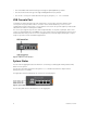
Hardware Overview 3 This section contains information about input/output aggregator (IOA) characteristics and modular hardware configurations. Internal Ports The Aggregator provides 8x10 Gigabit Ethernet internal ports. The internal ports are connected to a server through the Dell PowerEdge FX2 server chassis midplane. The Aggregator also provides an internal Ethernet interface — the out-of-band (OOB) interface, which is dedicated to switch management traffic on this port.
• Ports 9 and 10 are Fibre Channel (FC) type and support eight Gigabit FC, by default. • Ports 11 and 12 are Ethernet type and support 10 Gigabit Ethernet, by default. • You can also convert ports 9 and 10 to Ethernet type by using the port mode command. USB Console Port To manage the switch through an RS-232 serial interface, use the upper universal serial bus (USB) console port.
Table 2. System LED Displays System LED LED Color/Display Description Power Green Power is being supplied to the switch. Off The switch does not have power. Blue The switch is operating normally as a standalone switch or as a stack master. Off The switch is not the stack master. Amber A fault has occurred or the switch is booting. Status NOTE: The front-end ports also contain LEDs that provide information about the link status and traffic activity on a port.
4 Installation This switch installation procedure assumes that the Dell PowerEdge FX2 server chassis is installed correctly. For complete installation instructions, refer to the Dell PowerEdge FX2 server chassis Installation Guide. • AC/DC power cord — The cord reaches from the power outlet to the Utility-panel connector. • Cabling — The cabling is routed to avoid sources of electrical noise such as radio transmitters, broadcast amplifiers, power lines, and fluorescent lighting fixtures.
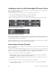
5 Installing and Configuring the Aggregator After you unpack the Aggregator, refer to the following flowchart for an overview of the steps you must follow to install the switch and perform the initial configuration. Figure 4.
Installing a switch in a Dell PowerEdge FX2 Server Chassis After you unpack the Aggregator, slide the switch into one of the open I/O module slots in the back of a Dell PowerEdge FX2 server chassis. The Dell PowerEdge FX2 server chassis is a 2U rack-mountable chassis that holds: • • Server modules: Eight quarter-width sledges or four half-width sledges.
2. Configure the terminal emulation software as follows: a. Select the appropriate serial port (for example, COM 1) to connect to the console. b. Set the data rate to 115200 baud. c. Set the data format to 8 data bits, 1 stop bit, and no parity. d. Set the flow control to none. e. Set the terminal emulation mode to VT100. f. Select Terminal keys for Function, Arrow, and Ctrl keys. Ensure that the setting is for Terminal keys (not Microsoft Windows keys). The default enable password is calvin.
6 Next Steps You can customize the Aggregator for use in your data center network. To perform additional switch configuration, do one of the following: • For remote OOB management, enter the OOB management interface IP address into a Telnet or secure shell (SSH) client and log in to the switch using the user ID and password to access the CLI. The default user ID is root and the default password is calvin. • For local management using the CLI, use the attached console connection.
Technical Specifications 7 The Aggregator is an I/O module and installed with the Dell PowerEdge FX2 server chassis for communication. NOTE: Replace the battery only with same or equivalent type. Dispose of the batteries according to the manufacturer's instructions. Table 4.