PowerEdge MX7000 Chassis Power Sequence Dell EMC Server & Infrastructure Jitendra Jagasia Michael Brown July 2018 A Dell EMC Technical White Paper
Revisions Date Description July 2018 Initial release The information in this publication is provided “as is.” Dell Inc. makes no representations or warranties of any kind with respect to the information in this publication, and specifically disclaims implied warranties of merchantability or fitness for a particular purpose. Use, copying, and distribution of any software described in this publication requires an applicable software license. Copyright © 2017 Dell Inc. or its subsidiaries.
Contents Revisions.............................................................................................................................................................................2 Executive summary.............................................................................................................................................................4 1 Introduction ...............................................................................................................................
Executive summary This technical whitepaper covers the Dell EMC MX7000 chassis power sequencing. It will discuss the things that happen after AC power has been applied to the chassis, what happens during the power ON sequence, as well as what happens when powering OFF the chassis. It will cover the lights and front panel indications during these sequences, as well as what order each component in the chassis is powered ON and OFF.
1 Introduction The Dell EMC MX7000 chassis is the latest chassis in the Dell EMC lineup, designed and constructed from the ground up as a brand new chassis. This new chassis has some important differences in how the system powers on from the older M1000e chassis, and this document will show the new power sequencing. In this document, we will reference the Right Control Panel (RCP), the OpenManage Enterprise Modular UI (OME), and OpenManage Mobile.
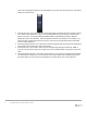
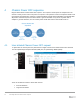
most of the management interfaces are still initializing. If you look at the front panel LCD, you will see loading screen like below 2. Chassis OFF state: In the OFF state, the chassis management controller still runs to provide external user control and management. Chassis can be powered ON either by pressing the chassis power button on the RCP, or using OpenManage Mobile (OMM) or OpenManage Enterprise Modular (OME).
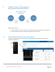
2 Chassis Power ON sequence. Diagram below shows chassis power ON sequence Chassis power ON occurs: 1. When requested by the user, either with a front panel power button or the various user interfaces 2. When AC power is restored, if chassis was ON when AC power was lost 2.
2.2 Auto Chassis Power ON If AC power is lost and later restored, the chassis will recover to the ON or OFF state that it was in prior to AC power loss. For example, if the chassis was ON prior to AC loss, after AC recovery, the chassis will automatically power back on. If the chassis was powering ON prior to AC loss (but had not completed power on), the chassis will power ON after recovery. If the chassis was powering OFF prior to AC loss, then the chassis will remain OFF when AC is recovered.
3 Chassis Powering ON sequence in detail. This section explains the order in which components are powered on. • • • • • 9 The first components which power ON are chassis infrastructure items: the power supplies, followed by fans and other critical internal components such as temperature sensors and the I/O Module microcontrollers. Once the infrastructure is up & running then all I/O Modules (IOMs) present in chassis are powered ON. After IOMs, any PowerEdge MX5016s present in chassis are powered ON.
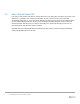
4 Chassis Power OFF sequence. Diagram below shows chassis Power OFF sequence. The sequence that we power off components in the chassis is exactly reverse order of the power on sequence in the previous section. One important detail is that normal power off requests are “graceful”. A graceful shutdown request means that IDRAC on individual sleds will perform and ACPI request to the OS to initiate a graceful shutdown.
4.2 Chassis Power OFF: Graceful shutdown. A graceful chassis power off sequence will cause chassis internal components to be powered OFF gracefully. In this mode if sled host cannot be shutdown gracefully then chassis will not power OFF, it will go back to chassis power ON state. Now user has option to either trigger graceful shutdown again or if user wants to shutdown chassis immediately then ungraceful shutdown can be triggered. User can initiate graceful shutdown from power button or from OME GUI.
5 Chassis Powering OFF sequence in detail. Diagram below shows chassis Powering OFF sequence in detail • • • • • 12 First we power OFF the all compute sleds present in the chassis. o If graceful shutdown power OFF sequence was initiated then sled will be gracefully turned OFF. If any sled fails to gracefully power off through the OS, the chassis will remain in the ON state.