Dell EMC OpenManage Enterprise-Modular Edition Version 1.10.20 for PowerEdge MX7000 Chassis User's Guide March 2020 Rev.
Notes, cautions, and warnings NOTE: A NOTE indicates important information that helps you make better use of your product. CAUTION: A CAUTION indicates either potential damage to hardware or loss of data and tells you how to avoid the problem. WARNING: A WARNING indicates a potential for property damage, personal injury, or death. © 2018 -2020 Dell Inc. or its subsidiaries. All rights reserved. Dell, EMC, and other trademarks are trademarks of Dell Inc. or its subsidiaries.
Contents Chapter 1: Overview...................................................................................................................... 8 Key features..........................................................................................................................................................................8 New in this release..............................................................................................................................................................
Troubleshooting in chassis.............................................................................................................................................. 40 Blinking LEDs......................................................................................................................................................................40 Interfaces to access OME-Modular..............................................................................................................................
Deleting templates............................................................................................................................................................ 68 Chapter 7: Managing identity pools............................................................................................. 69 Creating identity pools..................................................................................................................................................... 69 Editing identity pools.....
Chapter 12: Managing Fibre Channel IOMs................................................................................... 91 Chapter 13: Managing firmware................................................................................................... 92 Creating baselines............................................................................................................................................................. 92 Checking compliance........................................................
Retiring lead chassis.................................................................................................................................................. 110 Chapter 17: Troubleshooting....................................................................................................... 111 Storage................................................................................................................................................................................
1 Overview The Dell EMC OpenManage Enterprise Modular (OME-Modular) application runs on the PowerEdge M9002m management module (MM) firmware. OME-Modular facilitates configuration and management of a standalone PowerEdge MX chassis or group of MX chassis using a single Graphical User Interface (GUI). You can use OME-Modular to deploy servers and update firmware.
New in this release This release of OME-Modular supports: ● ● ● ● Customization of chassis backup file name Customization of host operating system reboot if a template deployment fails Hard reset of slot-based iDRAC interface from the Chassis Slots page Updating MX7000 components Supported platforms OME - Modular supports the following platforms and components: Platforms: ● ● ● ● ● ● ● ● ● ● ● ● PowerEdge MX7000 PowerEdge MX740c PowerEdge MX840c PowerEdge MX5016s PowerEdge MX5000s SAS Switch PowerEdge MX
Table 1. List of other documents for reference (continued) Name of the document Brief introduction of the document OpenManage Enterprise Modular Release Notes This document provides the latest updates to the system or documentation or advanced technical reference material that is intended for experienced users or technicians.
● Repository Manager—OME–Modular uses Repository Manager to create custom repositories in shared networks for creating catalogs. The catalogs are used for firmware updates. ● OME–Modular extracts the OpenManage SupportAssist logs from iDRAC for resolving issues.
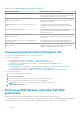
2 Updating the management module firmware The methods of updating the management module firmware and the MX7000 firmware components are described in this chapter. In MCM environment, perform the firmware update for all devices from the lead chassis. Also, select the IOMs and storage sleds as individual devices and not as chassis components, for a successful firmware update. NOTE: Ensure that you upgrade the OME-Modular firmware before upgrading OS10.
NOTE: Use the Add option on the Configuration > Firmware > Catalog Management option to download the catalog from the https://www.dell.com/support. Updating MX7000 components using OME-Modular 1.10.20 You can upgrade the following components of MX7000 using OME-Modular 1.10.20. The following table lists the new versions of the MX7000 components: Table 2. MX7000—OME-Modular 1.10.20 solution baselines Component Version iDRAC with Lifecycle Controller 4.11.11.11 Dell EMC Server BIOS PowerEdge MX740c 2.
Update the components in the following order: 1. iDRAC with Lifecycle Controller using OME-Modular 2. PowerEdge MX740c BIOS and PowerEdge MX840c Server BIOS 3. Update the device adapter operating system drivers followed by the device adapter firmware. Adapters—QLogic 27XX series Fibre Channel, QLogic 26XX series Fibre Channel, QLogic 41xxx series, Mellanox ConnectX-4 Lx Ethernet Adapter Firmware, Intel X710, XXV710, and XL710, Emulex Fibre Channel 4. OME-Modular 5.
A list of all the available chassis is displayed. b. In the list header, select the checkbox to select all the chassis on the current page. If there are multiple pages, then go to each page and select the checkbox. c. After all the chassis are selected, click Update Firmware. d. In the pop-up wizard, select the individual package and click Browse to select the OpenManage Enterprise Modular 1.10.10 DUP. e. After the DUP is uploaded, click Next and select the Compliance checkbox. f.
Sample output from a Chassis-group Master: IOM# show smartfabric cluster ---------------------------------------------------------CLUSTER DOMAIN ID : 159 VIP : fde1:53ba:e9a0:de14:0:5eff:fe00:1159 ROLE : MASTER SERVICE-TAG : MXWV122 MASTER-IPV4 : 100.69.101.170 PREFERRED-MASTER : 2. On the networking switch with the ROLE as MASTER, run the command, show smartfabric cluster member, to get the details of all the discovered switches in the OME-Modular chassis group.
a. Upgrade and reload both the VLT nodes simultaneously during the maintenance window, as data traffic may be affected during the upgrade. b. For the upgrade, use the CLI, explained in the section, Upgrading Networking Switch CLI. NOTE: During the image upgrade process in a VLT setup, when the VLT peers are running different software versions, no configuration changes should be done in any of the VLT peers. Ensure that both the nodes are upgraded to the same version before you make any configuration change.
Table 7. Command description Command Description OS10# image install image-url Install the software image. Example: OS10# image install image://filename.bin f. (Optional) View the status of the current software install in EXEC mode. Table 8. Command description Command Description OS10# show image status View the status of the current software install. g. Change the next boot partition to the standby partition in EXEC mode.
After all the IOMs are updated, the update process of all components in the MX7000 update procedure is complete. Verify that all expected data path links are up and passing traffic. If you experience network link or performance issues, power cycle (cold boot) the MX7000 chassis. For details, see Controlling chassis power.
3 Logging in to OME-Modular You can log in to OME–Modular as a local, Active Directory, or generic LDAP user. OME–Modular supports a maximum of two Active Directory or LDAP server configurations, each.
Logging in to OME-Modular as Active Directory or LDAP user To log in to OME–Modular as an Active Directory (AD) or LDAP user: 1. Add directory service 2. Import directory group 3. Log in with directory user credentials To add directory service: 1. From the menu bar in the OME–Modular web interface, click Application Settings > Users > Directory Services > Add. The Connect to Directory Service window is displayed. 2. Select AD or LDAP, and enter the appropriate information. 3.
● ● ● ● ● description and health status of the module. Click View Devices to see more details about the modules present in the chassis. Click View Slot Information to switch the display of the widget to slot information list. Slot information view—On the top left corner of the page, a list of modules present on the chassis is displayed showing slot information, health status and a link that goes into details. Modules in this list include compute, storage sleds, and IOMs.
● Recent Activity—Displays the most recent activities occurring in the lead chassis and the subsystems. Click All Activity, to view the Jobs page for the lead and member chassis. NOTE: If a member chassis is added to a chassis group based on a "Join Group" request from the member chassis, the status of the member chassis is displayed as "Unknown" for sometime, on the MCM dashboard.
Component Count Alert Policy 50 Identity pool 501 Network (VLAN) 214 Catalog 50 Baseline 50 To configure a chassis: 1. Click Devices > Chassis > View Details > Configure > Initial Configuration. The Chassis Deployment Wizard is displayed. NOTE: You can configure the chassis using an existing chassis profile. 2. In the Import Profile tab, click Import to open the Import Profile window. Enter details of the network share, where the chassis profile is located and click Import. 3.
● Quick Deploy Configure chassis power To configure the chassis power settings: 1. Click Devices > Chassis > View Details > Settings > Power. The Power configuration section is expanded. 2. Select Enable Power Cap to specify the maximum power consumption capacity for the chassis. The Power Cap limits the power consumption of the chassis. When the power cap is reached, the sleds are throttled based on their power priority. You can specify the capacity in Watts, BTU/h, or percentage.
To configure the chassis network: 1. Click Devices > Chassis > View Details > Settings > Network. The Network configuration section is expanded. 2. In the General Settings section, you can enable or disable NIC, Register with DNS, and Auto Negotiation. By default, the Enable NIC check box is selected. If you enable Register with DNS, then enter the DNS Name of the chassis that you want to register with a DNS server.
● ● ● ● ● ● ● ● Enable IPv6 Enable Autoconfiguration IPv6 Address Prefix Length Gateway Use DHCPv6 to Obtain DNS Server Addresses Statis Preferred DNS Server Static Alternate DNS Server NOTE: The static IPv6 IP address that is already configured is applied and displayed in OME–Modular when the configuration is changed from static to DHCP IP. 7. Enable or disable the VLAN for the chassis. You can configure the VLAN settings only if the Register with DNS check box is cleared.
8. Enable the remote RACADM session for the chassis. You can view the remote RACADM option on the web interface only if you have the chassis administrator privilege. NOTE: A log for remote RACADM session (login or logout) is displayed in the Audit Logs page, irrespective of the remote RACADM status. If the remote RACADM option is disabled, the feature does not work. NOTE: Any change in the attribute settings leads to IP drop or unavailability of the OME–Modular web interface for some time.
● ● ● ● ● ● English French Spanish German Japanese Chinese By default, the text is displayed in English. 11. Select the Enable Chassis Direct Access text box to enable accessing the MX7000 chassis from a host such as a laptop or server, using a USB On-The-Go (OTG) cable. If the Enable Chassis Direct Access check box is cleared, the existing chassis direct sessions are disconnected and the Chassis Direct LED turns off. When the feature is disabled, you cannot connect the laptop to the chassis.
Table 13. Chassis Direct—LED blink status and description (continued) Error code Chassis Direct LED blink status Description and resolution Resolution—If the issue persists, reattach the USB cable to the laptop or perform and AC power cycle of the chassis. 3 Amber The USB network link fails to come up owing to an issue on the host laptop. Resolution—If the issue persists, reattach the USB cable. 4 Turned off The USB network link is down as the USB cable is disconnected.
2. Enter and confirm the password to access the iDRAC user interface. The password can be up to 20 characters in length. NOTE: If any iDRAC IP configuration is modified, the SSO for the SLEDs is functional from the OME-Modular console only after the default inventory task or manual inventory refresh is complete. 3. In the Management IP section, select IPv4 Enabled to enable the IPv4 network settings and select the IPv4 Network Type. The available options are: ● Static ● DHCP 4.
NOTE: Maintain a minimum interval of two minutes between removing and inserting each device. NOTE: After a chassis power off, the compute SLEDs are polled based on the event from the chassis. Each event from the chassis triggers a health-poll. You may see multiple connection loss events from compute SLEDs. Creating chassis filters You can sort the list of chassis that are displayed on the Devices > Chassis page, using filters.
○ Create Chassis Group ○ Join Chassis Group ○ Initial Configuration ● Troubleshooting tasks: ○ Extract Log—You can extract the logs to a CIFS or NFS share, or a local drive on your system. ○ Diagnostic Commands ○ Reset management module ○ Terminate serial connection ● Turn-on or turn off LEDs using Blink LED. ● Back up, restore, export chassis profile, and perform failover. NOTE: After a chassis power off, the compute SLEDs are polled based on the event from the chassis.
Chassis groups You can group many chassis to form a multi-chassis management (MCM) group. An MCM group can have one lead chassis and 19 member chassis. You can use any management module to create an MCM group. The management module that is used for creating the MCM is the leader of the group, by default. The MCM group is of wired type, where the chassis is daisy-chained or wired through a redundant port on the management module.
Before creating an MCM group, ensure that the MX7000 management networks are wired together in a stacked configuration. The stacked configuration helps in surviving: ● ● ● ● A single network cable failure A single management module failure Power loss owing to any chassis in the stack Failover of a chassis in the stack NOTE: If any of the issues that are listed above occur, the management network access to all components in the daisychained group may be interrupted for up to 10 minutes.
Creating chassis groups To create a chassis group: 1. On the chassis dashboard, click Overview > Configure > Create Chassis Group. The Create a Group and Configure Lead Chassis wizard is displayed. 2. Enter a name and description for the chassis group you want to create. The group names can contain letters and numbers and must be fewer than 48 characters. However, the group names cannot contain spaces and special characters. 3. Select the onboarding permission type. 4.
4. Log in to the lead chassis and approve the request of the member chassis to join the chassis group. Assigning backup lead In a multi-chassis environment, the lead chassis may sometimes fail temporarily or retire. In such situations, it is necessary to nominate a member chassis in the MCM group as a backup to the lead chassis. The backup lead chassis is promoted as a lead chassis when the existing lead chassis fails or retires. 1. On the MCM dashboard, click Configure > Edit Backup Lead Settings.
Retiring lead chassis You can use the retirement process of the existing lead chassis to make it a member chassis of the existing group or a standalone chassis. 1. On the MCM dashboard, click Configure > Retire Lead Chassis. The Retire Lead Chassis window is displayed. 2. Select one of the following options: ● Make it a member of the current group. ● Make it a stand-alone chassis. 3. Click Retire. Also, see the section, Use case scenarios.
2. Click Confirm to proceed. Backing up chassis Back up the chassis and compute sled configuration for later use. To backup the chassis, you must have administrator access with the device configuration privilege.
You can check the status and details of the restore process on the Montitoring > Jobs page. Exporting chassis profiles You can export chassis profiles for cloning the settings to other chassis. To export the chassis profile: 1. On the OME–Modular home page, click More Actions > Export Profile. The Export Profile window is displayed. 2. Select the Share Type. 3. Enter the network share address and path. 4. If the Share Type is CIFS, enter the Domain, User Name, and Password to access the shared location. 5.
Table 14. Management module Interfaces Interface Description Web interface Provides remote access to OME–Modular using a graphical user interface. The web interface is built into the OME–Modular firmware and is accessed through the NIC interface from a supported web browser on the management station.
Table 14. Management module Interfaces (continued) Interface Description 1. Download the OME-Modular MIB file from the https://www.dell.com/support. 2. Use MIB walker tool to get supported information using OIDs. NOTE: SNMP SET is not supported. Serial You can use the serial interface to access OME–Modular by connecting the micro USB port on the rear of the management module to a laptop and opening a terminal emulator.
● Category ● Subcategory ● Message Select an alert to view the summary of the alert. You can also perform the following activities on the Alerts page. ● ● ● ● ● Acknowledge Unacknowledge Ignore Export Delete Viewing chassis hardware logs The logs of activities performed on the hardware components associated with the chassis are displayed on the OME–Modular Hardware Logs page. The log details that are displayed include severity, message ID, category, timestamp, and description.
Configuring OME–Modular web server 1. Click Application Settings > Network > Web Server Configuration. 2. Ensure that the Enable Web Server option is selected. 3. Enter the timeout value in minutes. 4. Enter the port number for the web server. You can enter a port number in the 10-65535 range. The default port number is 443.
Configuring OME–Modular proxy settings 1. Click Application Settings > Network > Proxy Configuration. 2. Select Enable HTTP Proxy Settings. 3. Enter the proxy address and the port number. 4. If the proxy requires authentication, select Enable Proxy Authentication and enter the credentials. You can enable proxy authentication only if the Enable HTTP Proxy Settings option is selected. 5. Enter the proxy user credentials. Changing device naming and preference 1.
Table 15. Ports and protocols that are supported in OME-Modular (continued) Port number Protocol Port type Maximum encryption level Source Direction Destination Usage 161* SNMP UDP None External Application In OpenManage Enterprise Modular For SNMP queries. 162 SNMP UDP None External Application In/Out OpenManage Enterprise Modular Send SNMP traps and receive Informed Request. 443 HTTPS TCP 128-bit SSL External Application In/Out OpenManage Enterprise Modular Web GUI.
Viewing and editing user accounts 1. Click Application Settings > Users On this page, you can view a list of users accounts and their roles, the user types, and whether the account is enabled or not. 2. Select a user and click Edit on the right side of the page. 3. Edit the required settings. NOTE: You can change only the password of the default "root" account. Adding users 1. Click Application Settings > Users 2. Click Add. 3. Enter the Username. The default username is "root", and you cannot edit it.
6. Log out and log in again using the modified password to ensure that the login is successful. 7. Remove the jumper and reinsert it into the default positions—2 and 3. Recovering passwords in dual OME-Modular controllers 1. From the chassis, remove both the OME-Modular controllers. 2. On one of the modules, locate the Jumper, see the board location—P57 RESET PASSWORD, and then insert the Jumper. 3. Reinsert only the controller, where the Jumper is installed, into the chassis. 4.
Table 16. User roles and privileges (continued) User Role Chassis Administrator Compute Manager Storage Manager Fabric Manager Viewer Managing firmware catalogs and baseline policies Yes Yes Yes Yes No Power budget configuration and management Yes No No No No Managing user sessions You can view and terminate existing user sessions using the User Sessions page, if you have the chassis administrator privilege. Viewing user sessions On the Users page, click User Sessions.
NOTE: The directory name can have a maximum of 255 characters. 4. From the Domain Controller Lookup, select DNS or Manual. 5. Enter the DNS domain name in the Method field. NOTE: If the domain controller lookup type is Manual, enter the Fully Qualified Domain Name (FQDN) or IP addresses of the domain controller. a. If you have selected the directory type as AD, enter the domain name in the Group Domain field. NOTE: This option is displayed only if the directory type is AD.
2. Select Enable IP Range. 3. Enter the IP range in the CIDR format. For IPv4, enter the IP address in the format—192.168.100.14/24. For IPv6, enter the IP address in the format— 2001:db8::/24. Configuring login lockout policy 1. Click Application Settings > Security > Login Lockout Policy. 2. Select By User Name to enable user account-based lockout. Select By IP Address to enable IP address-based lockout. 3. Enter the lockout details: a. Lockout Fail Count: The number of failed login attempts.
● OME–Modular generates a new SSL certificate with validity from build_time till (build_time +10 years) only during first boot scenarios such as firmware update, racresetcfg, and FIPS mode changes. NOTE: Only the users with the chassis administrator privileges can generate certificate signing requests. Configuring alerts This section allows you to configure the email, SNMP, and the syslog settings to trigger alerts. Configuring email alerts 1. Click Application Settings > Alerts. 2.
Configuring sys log alerts You can configure up to four sys log destinations. To configure system log alerts, perform the following steps: 1. Click Application Settings > Alerts > Syslog Configuration. 2. Select the Enabled check box corresponding to the required server. 3. Enter the destination address or the hostname. 4. Enter the port number.
4 Managing compute sleds OME–Modular enables you to allocate and manage compute sleds to balance workload demands. You can view the list and details of compute sleds on the Compute page. The details are—health, power state, name, IP address, service tag, and model of the chassis. You can also select a compute sled to view the graphical representation and summary of the compute sled, on the right side of the Compute page. Select a compute sled from the list to view a summary of the sled on the right side.
● Chassis Information—Displays the details of the chassis on which the compute sled is placed. Click View All to view the list of all activities in the Jobs page. ● Recent Alerts—Displays the number and details of the tasks that are performed in the compute sled. Click View All to view the list of all alerts that are related to the compute sled on the Compute > Alerts page. ● Recent Activity—Displays the status of the jobs that are performed in the compute sled.
○ Associate with Slot—You can associate profiles to blade servers. The profile is extracted from the server and is attached to the slot containing the server. ○ Migrate Profile—You can migrate a profile from one server to another. The system unassigns the identity from the first server before the migration. If the unassignment fails, the system displays a critical error. You can override the error and force the migration to a new server.
NOTE: While replacing compute sleds, ensure that the: ● Compute sled is turned off and the compute nodes in the chassis contain PERC or HBA controllers. ● SAS IOMs and storage sleds are installed in the chassis. ● When you replace a compute sled, with a service tag, with a compute sled of another service tag, and the storage sleds are mapped to the compute node slot, the power on the particular compute sled is turned off.
NOTE: If the storage controller cards are absent in iDRAC, the storage enclosure details are not displayed on the Compute > View Details > Hardware > Storage Enclosure page. Viewing compute firmware You can view the firmware list for the compute in the compute Firmware page. Click Devices > Compute > View Details > Firmware. The details include name of the device or component, impact assessment, current version, and baseline version.
5 Managing storage This chapter describes the Storage and IOM features of OME–Modular. It also provides details about performing various storage-related tasks. The SAS IOMs manage the storage enclosures. SAS IOMs facilitate communication between storage and compute sled and also help in assigning the storage to the compute sleds.
1. From the Devices drop-down menu, select Storage. 2. Select the storage sled. 3. Click Blink LED and click Turn On. To turn off the LED blinking: 1. From the Devices drop-down menu, select Storage. 2. Select the storage sled. 3. Click Blink LED and click Turn Off. You can pull out the storage sled trays from the chassis to access the storage sled drives.
● Enclosure-Assigned—In this mode, you can assign an entire storage sled to one or more compute node slot. NOTE: You cannot assign storage when a redundant SAS IOM setup is temporarily degraded to non-redundant state. NOTE: The storage enclosure is assigned to the slots of the compute slots and not to the sled itself. If a compute sled is replaced with another sled on the same slot, then the storage enclosure gets assigned to the new sled automatically.
After replacing PERC card wait for some time for OME–Modular to get the new inventory details from iDRAC before performing the assignment operation. Else, refresh the inventory on the Compute page, manually. Replacing storage sleds When you remove a storage sled from one slot and insert it into another slot on the chassis, the mapping on the new slot is used for the storage sled.
Managing SAS IOMs The internal connection of the storage subsystem is called "Fabric C", which serves as a communication mode between compute sleds and storage enclosures. The "Fabric C" is used for SAS of FC storage connectivity and includes a midplane. SAS IOMs allow creating storage assignments in which you can map storage enclosure drives or whole storage enclosures to compute sleds. SAS IOMs provide multi-path input out access for compute sleds to drive elements.
NOTE: If you perform the Clear operation on a SAS IOM, the IOM becomes active, if it is not already active and, the storage configuration on both the SAS IOMs is cleared. NOTE: Resolve any suboptimal health of the IOM, other than firmware mismatch, before updating the firmware. This action ensures that the firmware is updated without downgrading the health of the SAS IOM. Force active You can use More Actions > Force Active to perform a failover on a "Passive" or "Degraded" switch.
6 Managing templates OME–Modular allows you do configure servers based on templates. A server template is a consolidation of configuration parameters extracted from a server and used for replicating the configuration to multiple servers quickly. A server profile is a combination of template and identity settings that are applied to a specific or multiple servers, or saved for later use. You must have the template management privilege to create templates.
Creating templates You can create templates in the following ways: ● Clone from an existing server—Reference Device ● Import from an external source—Import from File To create a template from a reference device: 1. On the Deploy page, click Create Template and select From Reference Device. The Create Template wizard is displayed. 2. Enter the name and description for the template and click Next. The Reference Device tab is displayed. 3.
If the template has identity attributes, but is not associated with a virtual identity pool, a message is displayed that the physical identities are used for the deployment. Else, the Deploy Template wizard is displayed. 2. Select the target device on which you want to deploy the template, configure the iDRAC management IP settings, select the Do not forcefully reboot the host OS option, and schedule the deployment. The compute sled reboots gracefully or non-gracefully, based on the selection.
Exporting templates You can export the templates to a network share or a local drive on your system. To export a template: On the Deploy page, select the template that you want to export and click Export. A message is displayed to confirm the export action. The template is exported in .xml format to a local drive on your system or a network share. Deleting templates To delete templates: 1. On the Deploy page, select the template that you want to delete and click Delete.
7 Managing identity pools Identity pools are used in template-based deployment of servers. They facilitate virtualization of network identities that are required for accessing systems using Ethernet, iSCSI, FCoE, or Fibre Channel (FC). You can enter the information that is required for managing the I/O identities. The identities, in turn, are managed by chassis management applications such as OME– Modular.
If the identity is assigned, the information about the assigned server and NIC Identifier is displayed. If the identity is reserved, the information about the assigned slot in the chassis is displayed. You can create an identity pool with only the name and description and configure the details later. NOTE: You can clear identities by disabling the I/O Identity Optimization option in iDRAC. To create identity pools: 1. Click Configuration > Identity Pools.
Editing identity pools You can modify the number of entries in the identity pool. However, you cannot reduce the size of the identities that are already assigned or reserved. For example, in a pool of 100 MAC addresses, if 94 of the addresses are assigned or reserved, you cannot reduce the number of MAC addresses to less than 94. To edit an identity pool: 1. On the Identity Pools page, select the identity pool and click Edit. The Edit Identity Pool window is displayed. 2. Make the required changes.
8 Ethernet IO Modules The MX7000 supports the following Ethernet I/O Modules (IOMs): ● Managed Ethernet switches: ○ MX9116n Fabric Switching Engine ○ MX5108n Ethernet Switch ● Unmanaged devices: ○ MX7116n Fabric Expander Module ○ PowerEdge MX 25Gb Ethernet Pass-Through Module ○ PowerEdge MX 10GBASE-T Ethernet Pass-Through Module Ethernet IOMs are supported in Fabrics A and B. For details about the supported IOM slots, see Supported slot configurations for IOMs.
Topics: • • Viewing hardware details Configuring IOM settings Viewing hardware details You can view information for the following IOM hardware: ● ● ● ● FRU Device Management Info Installed Software Port Information NOTE: If the physical port is added as part of the port channel, it is listed under the port channel group instead of the physical port. NOTE: The URL attribute is displayed as "N/A" on the Hardware > Device Management Info page for FC IOMs, owing to device capability limitations.
4. In the IPv6 Settings section, select Enable IPv6. 5. Enter the IPv6 Address, select the Prefix Length. The IPv6 Address, Prefix Length, and Gateway options are enabled only if the Enable Autoconfiguration check box is cleared. 6. Enter the Gateway for the management port. The IPv6 Address, Prefix Length, and Gateway options are enabled only if the Enable Autoconfiguration check box is cleared.
Configuring ports In SmartFabric mode, you can configure breakout and admin status, and MTU size for IOMs. You can configure port breakout only for port groups. NOTE: Ensure that the peer FC port has a fixed speed and matches the speed of the IOM FC port for the link to come up. To configure breakout: 1. Click Devices > I/O Modules > View Details > Hardware > Port Information. 2. Select the port group and click Configure Breakout. The Configure Breakout window is displayed. 3. Select the Breakout Type.
9 MX Scalable Fabric architecture The scalable fabric architecture ties multiple MX7000 chassis into a single network domain to behave like a single logical chassis from a networking perspective.
Additional chassis only have FEMs and the appear as the image below. Table 18. Fabric topology Chassis Slot Module Chassis 1 A1 MX9116n FSE A2 MX7116n FEM A1 MX7116n FEM A2 MX9116n FSE A1 MX7116n FEM A2 MX7116n FEM Chassis 2 Chassis 3-10 You can also use Fabric B to create a second scalable fabric: Restrictions and guidelines The following restrictions and guidelines are applicable when building a scalable fabric: ● Mixing switch types in the same fabric is not supported.
● IOM placement for each scalable fabric must be the same within the same chassis. For example, if the FSE for the first scalable fabric is in Slot A1, then the second FSE must be in slot B1 in the same chassis, and so on. ● For chassis that only contain FEMs, all four FEMs must connect to the same chassis with the FSEs. The fabric B FEMs cannot be connected to FSEs in a different chassis as the fabric A FSEs. Recommended connection order Any QSSFP28-DD port on the MX9116n can be used for any purpose.
10 SmartFabric Services SmartFabric Services is a capability of Dell EMC Networking OS10 Enterprise Edition running on Ethernet switches designed for the PowerEdge MX platform. A SmartFabric is a logical entity containing a collection of physical resources such as servers and switches and logical resources —networks, templates, and uplinks.
• • Deleting fabric VLANs for SmartFabrics and FCoE Guidelines for operating in SmartFabric mode The guidelines and restrictions while operating in SmartFabric mode are as follows: ● When operating with multiple chassis, ensure that the switches in A1/A2 or B1/B2 in one chassis are interconnected only with other A1/A2 or B1/B2 switches respectively. Connecting switches that are placed in slots A1/A2 in one chassis with switches in slots B1/B2 in another chassis is not supported.
In SmartFabric mode, ports 9 and 10 are automatically configured in a VLT at 40GbE speed. For port 10, use a cable or optic that supports 40GbE and not 100GbE. 2 x MX9116n Fabric Switching Engines in the same chassis Use this placement in environments with a single chassis. The switches must be placed in either slots A1/A2 or slots B1/B2. A SmartFabric cannot include a switch in Fab A and a switch in Fab B.
NOTE: You cannot select the ports, and the connection topology is enforced by SmartFabric Services. NOTE: VLT is supported only on Ethernet and not on FCoE. Physically separate uplinks for LAN and FCoE traffic are required for MX5108n and MX9116n switches. Upstream network switch requirements It is recommended, but not required, that PowerEdge MX switches are connected to a pair of redundant upstream switches.
2. If the host OS is Windows, the LACP timer MUST be set to “slow” (also referred to as “normal”) For the list of supported operating systems, see Dell EMC PowerEdge MX7000 Enclosure Installation and Service Manual. NOTE: In the fabric mode, if an LACP team is created with four port and you want to delete two ports from the LACP team, you must delete the entire LACP team and create a new LACP team with two ports.
The Create Fabric window is displayed. 3. Enter Name and Description, and then click Next. 4. Select the Design Type from the drop-down. The available options are: ● 2xMX5108n Ethernet Switches in same chassis ● 2xMX9116n Fabric Switching Engines in same chassis ● 2xMX9116n Fabric Switching Engines in different chassis Based on the design type selected, the options to select the chassis and the switches—A and B, are displayed. 5. Select the chassis and switches. The cabling image is displayed. 6.
If you are required to configure new network other than the existing ones, click Add Network and enter the network details. For more details see, Adding Network. Adding network You can use the Fabric and Configuration > Network pages to add networks. For more information, see Defining networks. To add a new network from the Fabric page: 1. From the Devices drop down, select Fabric. The Fabric page is displayed. 2. From the fabrics table, select the fabric and click View Details.
3. Make the necessary changes to the Name and Description fields. Deleting uplinks To delete an uplink: 1. From the Devices drop down, select Fabric. The Fabric page is displayed. 2. In the fabrics table, select any fabric and click View Details. 3. In the uplinks table, select the uplink to be deleted. 4. Click Delete. Click Yes to confirm the deletion. Deleting fabric To delete an existing fabric: 1. From the Devices drop-down, select Fabric. The Fabric page is displayed. 2.
Editing VLANs You can add or remove VLANs on the deployed servers in a SmartFabric. To add or remove VLANs: 1. From the menu, click Devices > Fabric. 2. Select the fabric for which you want to add or remove the VLAN. 3. In the left pane, select Servers and select the required servers. 4. Click Edit Networks. 5. Select one of the following options: ● NIC teaming from LACP ● No Teaming ● Other 6. Define the tagged and untagged VLANs to modify the VLAN selections as required. 7.
11 Managing networks You can configure logical networks that represent your environment, for the tagged and untagged VLANs. These logical networks are used to provision the appropriate VLANs on the associated switch port for the physical server NIC port. NOTE: VLANs are only assigned to servers connected to switches in Fabric mode. For servers connected to switches in Full Switch mode, the VLAN information is ignored. In tagged networks, a port handles multiple VLANs.
Table 22. Network traffic types - QoS settings (continued) Network Traffic Type Description QoS Setting Storage - FCoE Used for FCoE VLANs 5 Storage - Data Replication Used for VLANssupporting storage data replication such as for VMware VSAN 5 VM Migration Used for VLANs supporting vMotion and similar technologies 5 VMWare FT Logging Used for VLANs supporting VMware Fault Tolerance 5 Defining networks To configure a logical network: 1. Click Configuration > Networks.
Deleting network configurations To delete a network: On the Networks page, select the network and click Delete. If the network is associated with a fabric uplink, a warning message is displayed that deleting the network results in loss of connectivity.
12 Managing Fibre Channel IOMs The MXG610s Fibre Channel (FC) switch is designed for mission critical applications accessing data on external storage. It is optimized for flash storage and virtualized server environments. The FC switch enables organizations to dynamically scale connectivity and bandwidth Ports-on-Demand (PoD). It enhances operations with consolidated management and simple server and storage connectivity. OME–Modular makes the management of the MXG610s simple.
13 Managing firmware The firmware feature in OME–Modular helps you to update the firmware of all the components in the chassis. The components include compute sleds, ethernet IOMs, storage IOMs, and SAS IOMs. The firmware updates can be sources from the Dell web site or a custom repository setup using Repository Manager. You must have the chassis administrator role and the device update privilege for the chassis to update the firmware on the chassis.
The Add Firmware Catalog window is displayed. 4. Select the catalog source. 5. In the Create Firmware Baseline window, select the devices and groups for which you want to create the baseline. After the baseline is created, a message is displayed and a compliance check is performed on the baseline. The status of the job is displayed on the Firmware page. NOTE: If the baseline is created from the catalog, the information of the associated baseline is displayed.
downloading it, the modified catalog is not downloaded. If the repository type is NFS and the catalog file is not available on the specified NFS server, the system uses the catalog file that was last fetched. To view the list of catalogs: On the Firmware page, click Catalog Management. The Catalog Management page is displayed. You can select a catalog to view the summary on the right-side.
The available options are: ● Manually ● Automatically The default mode is manual. 5. Select the Update Frequency. ● Daily ● Weekly The time can be in HH:MM format. Editing catalogs You can only modify the catalog name, network share address, and catalog filepath. To edit catalogs: 1. On the Catalog Management page, select the catalog that you want to edit and click Edit. The Edit Firmware Catalog window is displayed. 2. Make the required changes.
Rolling back firmware If you are not convinced with the firmware update of a device or component, you can roll back the update to the version before the update. The rollback option is enabled only if OME–Modular can access the firmware package of the previous version. The following methods can be used to enable the access: ● A Device that has the rollback version (or N-1 version) that matches the previous version. Not all devices support a rollback or N-1 version.
14 Monitoring alerts and logs You can view and manage the alerts that are generated in the management system environment. You can filter alerts and perform the appropriate actions. Every chassis in the MCM group receives Fabric alerts, irrespective of whether the MX5108N or MX9116N IOMs present in the chassis to accommodate new MX5108N or MX9116N IOMs in the chassis. To view the alerts page, from the menu bar, click Alerts.
Acknowledging alert logs You can acknowledge alert logs that are not already acknowledged. Acknowledging an alert prevents storing the same event in the system. For example, if a device is noisy and is generating the same event multiple times, you can ignore further recording of the alert by acknowledging the events that are received from the device. And, no events of the same type are recorded further.
● ● ● ● Edit alert policies Enable alert policies Disable alert policies Delete alert policies OME–Modular also offers pre-defined alert policies for monitoring the systems, after the alert destinations are configured. Creating alert policies To create an alert policy: 1. From the menu bar, click Alerts > Alert Policies > Create. The Create Alert Policy wizard is displayed. 2. Enter the name and description for the alert policy. 3. Select Enable Policy to activate the alert policy and click Next.
Editing alert policies You can edit alert policies. To edit alert policies: On the Alert Policies page, select the alerts that you want to edit and click Edit. A confirmation message is displayed. Disabling alert policies You can disable alert policies that are enabled. You can disable more than one alert policy at a time. To disable alert policies: On the Alert Policies page, select the alerts that you want to disable and click Disable. A confirmation message is displayed.
● Severity—To view all alerts with specific severity level. Selections that are made in the filters are applied at real time. 4. To reset the filters, click Clear All Filters.
15 Monitoring audit logs The audit log feature in OME–Modular enables you to monitor log entries related to: ● ● ● ● Log in attempts Appliance setup Chassis configuration change using RESTful API Change in alert filter configuration On the Audit Log page, you can perform the following tasks: ● Sort the audit logs using the Advanced Filter. ● Export all the audit logs in .csv format to a network share or local drive on your system.
Monitoring jobs You can view the status of and details of jobs that are initiated in the chassis and its subcomponents, on the Jobs page. The jobs include firmware update and inventory refresh for devices. To view the Jobs page, from the menu bar, click Monitor > Jobs. You can perform the following tasks on the Jobs page: ● ● ● ● ● ● ● Filter jobs using Advanced Filter View a summary of the job.
○ MCM OffBoarding ○ Backup ○ Profile Update ○ Quick Deploy ○ MCM OnBoarding ○ MCM Group ● Last Run Start Date and Last Run End Date—To view jobs based on the last run period. Selections made in the filters are applied at real time. To reset the filers click Clear All Filters. Viewing job details The Fabric Manager on-boarding is initiated when a Fabric Manager failover occurs in the IOM cluster.
To stop jobs: On the Jobs page, select the ongoing jobs that you want to stop and click Stop. A message is displayed prompting you to confirm the operation. Enabling jobs You can enable jobs that are disabled. To enable jobs: On the Jobs page, select the disabled jobs that you want to enable and click Enable. A confirmation message is displayed and the state of the selected jobs changes to "Enabled". Disabling jobs You can disable jobs that are enabled.
16 Use case scenarios Use case scenarios for the backup lead chassis feature are described in this chapter. Topics: • • Assigning backup to the MCM Lead Scenarios when backup lead can take over as lead chassis Assigning backup to the MCM Lead The backup lead chassis feature facilitates management of systems in the chassis group when the existing lead chassis fails.
Initially, the backup health status is displayed as "Critical" while the configuration data is being synchronized before changing to "OK". Wait for the backup health to transition to "OK" before proceeding. If the backup health continues to report "Critical" or "Warning" even after 30 minutes of the assign task, it is an indication that there are persistent communication issues. Unassign the backup and repeat the Step 5 to choose another member as the new backup.
Figure 2. Network and power outage—flowchart The alert, CDEV4007, is related to network or power issues that can be classified as: ● Intermittent/recoverable issues—Momentary power or network outages. The administrator can identify these types of failures and perform recovery actions locally or remotely. Do not promote the backup lead. Allow the lead chassis to recover connectivity automatically or the administrator fixes the power or network issues.
1. Before running the "promote" task on the backup lead chassis: a. The "promote" task is a disruptive operation and must be used only when there are no means to recover the inaccessible lead chassis. In partial failures of the lead chassis, for example; if only the management modules are nonresponsive, but the computes are working, running the promote task disrupts workloads that are still running on the lead chassis computes.
iv. Do not delete fabrics from the old lead chassis as deleting the fabrics can lead to network loss once the old lead is added back to the network. v. On the old lead, run a force “reset configuration” using the following REST API payload: URI: /api/ApplicationService/Actions/ApplicationService.ResetApplication Method: POST Payload: {"ResetType": "RESET_ALL", "ForceReset": true} d. Relocate the working components of the old lead to other chassis in the group: i.
17 Troubleshooting This section describes the tasks for troubleshooting and resolving issues using the OME–Modular user interface.
3. An inconsistency is detected in the subcomponent firmware. Drives on compute sled are not visible 1. If the compute sled is configured with a PERC controller and the drives have been reseated or moved, they are rediscovered as "Foreign". 2. If the drives are removed from the storage sled, they cannot be discovered. 3. If a storage sled is replaced, the storage configuration of the earlier sled cannot be applied to the replaced sled. Storage configuration cannot be applied to SAS IOMs 1. 2. 3. 4.
A Recommended slot configurations for IOMs The table below contains the recommended IOM slot configurations. Table 23.
Table 24.