Dell PowerEdge R430 Owner's Manual Regulatory Model: E28S Series Regulatory Type: E28S001 November 2020 Rev.
Notes, cautions, and warnings NOTE: A NOTE indicates important information that helps you make better use of your product. CAUTION: A CAUTION indicates either potential damage to hardware or loss of data and tells you how to avoid the problem. WARNING: A WARNING indicates a potential for property damage, personal injury, or death. © 2014 - 2020 Dell Inc. or its subsidiaries. All rights reserved. Dell, EMC, and other trademarks are trademarks of Dell Inc. or its subsidiaries.
Contents Chapter 1: Dell PowerEdge R430 system overview.........................................................................8 Supported configurations for the PowerEdge R430 system.................................................................................... 8 Front panel ........................................................................................................................................................................... 9 Front panel features of a 4 x 3.
Expanded operating temperature............................................................................................................................ 37 Expanded operating temperature restrictions......................................................................................................38 Chapter 4: Initial system setup and configuration........................................................................39 Setting up your system............................................................
Removing a 3.5-inch hard drive blank.....................................................................................................................91 Installing a 3.5-inch hard drive blank...................................................................................................................... 92 Removing a 3.5-inch cabled hard drive carrier.................................................................................................... 93 Installing a 3.
Removing a redundant power supply unit........................................................................................................... 136 Installing a redundant power supply unit..............................................................................................................137 Removing a cabled power supply unit.................................................................................................................. 138 Installing a cabled power supply unit.................
Troubleshooting power supply units............................................................................................................................178 Troubleshooting power source problems............................................................................................................. 178 Power supply unit problems.................................................................................................................................... 179 Troubleshooting cooling problems....
1 Dell PowerEdge R430 system overview The Dell PowerEdge R430 systems are 2U rack servers that support up to two Intel Xeon E5-2600 v3 or Xeon E5-2600 v4 processors, up to 12 DIMMs, and ten hard drives or solid state drives (SSDs).
Front panel The front panel provides access to the features available on the front of the server, such as the power button, NMI button, system identification tag, system identification button, and USB and VGA ports. The diagnostic LEDs or the LCD panel is prominently located on the front panel. The hot swappable hard drives are accessible from the front panel. Front panel features of a 4 x 3.5-inch hard drive system Figure 2. Front panel features of a 4 x 3.5-inch hard drive system 1. 3. 5. 7. 9. 11.
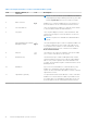
Table 1. Front panel features of a 4 x 3.5-inch hard drive system Item Indicator, Button, or Connector Icon Description NOTE: To reset the iDRAC (if not disabled on the iDRAC setup page by pressing F2 during system boot), press and hold the System ID button for more than 15 seconds. 4 Video connector Enables you to connect a display device to the system. For more information, see the Technical specifications section.
Front panel features of the 4 x 3.5-inch cabled hard drive system Figure 3. Front panel features of the 4 x 3.5 inch cabled hard drive system 1. 3. 5. 7. 9. Power button System identification button Diagnostic indicators Information tag Optical drive 2. 4. 6. 8. NMI button Video connector USB port (2) Hard drives Table 2. Front panel features of the 4 x 3.
Table 2. Front panel features of the 4 x 3.5-inch cabled hard drive system Item Indicator, Button, or Connector Icon Description 7 Information tag The Information tag is a slide-out label panel that contains system information such as Service Tag, NIC, MAC address, and so on. If you have opted for the secure default access to iDRAC, the Information tag also contains the iDRAC secure default password. 8 Hard drives Up to 4 x 3.5 inch cabled hard drives.
Table 3. Front panel features of a 8 x 2.5 inch hard drives or SSDs system Item Indicator, Button, or Connector Icon Description NOTE: Use the NMI button only if directed to do so by qualified support personnel or by the operating system documentation. 3 System identification button The System Identification (ID) button is available on the front and back panels. Press the button to identify a system in a rack by powering on or off the system ID LED.
Front panel features of the 10 x 2.5-inch hard drives or SSDs system Figure 5. Front panel features of the 10 x 2.5-inch hard drives or SSDs system 1. USB management port/iDRAC managed USB port 3. Power button 5. System identification button 2. Diagnostic indicators 4. NMI button 6. Hard drives Table 4. Front panel features of the 10 x 2.
Table 4. Front panel features of the 10 x 2.5-inch hard drives or SSDs system Item Indicator, Button, or Connector Icon Description Enable you to install drives that are supported on your system. For more information about drives, see the Technical specifications section. LCD panel The LCD panel of your system provides system information, status, and error messages to indicate if the system is functioning correctly or if the system needs attention.
Viewing Home screen The Home screen displays user-configurable information about the system. This screen is displayed during normal system operation when there are no status messages or errors. When the system turns off and there are no errors, LCD enters the standby mode after five minutes of inactivity. Press any button on the LCD to turn it on. Steps 1. To view the Home screen, press one of the three navigation buttons (Select, Left, or Right). 2.
Option Description Name Displays the name of the Host, Model, or User String for the system. Number Displays the Asset tag or the Service tag for the system. Power Displays the power output of the system in BTU/hr or Watts. The display format can be configured in the Set home submenu of the Setup menu. Temperature Displays the temperature of the system in Celsius or Fahrenheit. The display format can be configured in the Set home submenu of the Setup menu.
Table 6. Redundant PSU back panel features Item Indicator, Button, or Connector Icon Description 1 Serial connector Enables you to connect a serial device to the system. For more information, see the Technical specifications section. 2 Ethernet port 1 Use the Ethernet port to connect Local Area Networks (LANs) to the system. For more information about the supported Ethernet ports, see the Technical specifications section.
Table 6. Redundant PSU back panel features Item Indicator, Button, or Connector 12 Ethernet port 3 13 Ethernet port 4 14 Power supply unit (PSU1 and PSU2) Icon Description Use the Ethernet port to connect Local Area Networks (LANs) to the system. For more information about the supported Ethernet ports, see the Technical specifications section. Up to two 550 W redundant AC power supplies. Cabled PSU back panel features Figure 8. Cabled PSU back panel features 1. 3. 5. 7. 9. 11. 13.
Table 7. Cabled PSU back panel features Item Indicator, Button, or Connector Icon Description 5 PCIe expansion card slots (2) Enables you to connect two PCI Express expansion cards. 6 Video connector Enables you to connect a display device to the system. For more information, see the Technical specifications section. 7 Ethernet port 2 Use the Ethernet port to connect Local Area Networks (LANs) to the system.
Diagnostic indicators The diagnostic indicators on the system indicate operation and error status. Diagnostic indicators on the front panel NOTE: No diagnostic indicators are lit when the system is turned off. To start the system, plug it into a working power source and press the power button. Table 8. Diagnostic indicators Icon Description Condition Health indicator The indicator turns solid blue if the None required. system is in good health.
Hard drive indicator codes Each hard drive carrier has an activity indicator and a status indicator. The indicators provide information about the current status of the hard drive. The activity LED indicates whether hard drive is currently in use or not. The status LED indicates the power condition of the hard drive. Figure 9. Hard drive indicators 1. Hard drive activity indicator 2. Hard drive status indicator 3.
uSATA SSD indicator codes Figure 10. uSATA SSD indicators 1. uSATA SSD activity indicator 2. uSATA SSD status indicator 3. uSATA SSD NOTE: If the SSD is in the Advanced Host Controller Interface (AHCI) mode, the status indicator (on the right side) does not function and remains off. Table 10. Drive status indicator codes Drive-status indicator pattern Condition Flashes green twice per second Identifying drive or preparing for removal. Off Drive ready for insertion or removal.
NIC indicator codes The NIC on the back panel has an indicator that provides information about the network activity and link status. The activity LED indicates whether the NIC is currently connected or not. The link LED indicates the speed of the connected network. Figure 11. NIC Indicator Codes 1. link indicator 2. activity indicator Table 11. NIC indicators Convention Status Condition A Link and activity indicators are off. The NIC is not connected to the network. B Link indicator is green.
Figure 12. Internal dual SD module (IDSDM) 1. LED status indicator (2) The following table describes the IDSDM indicator codes: Table 12. IDSDM indicator codes Convention IDSDM indicator code Description A Green Indicates that the card is online. B Flashing green Indicates rebuild or activity. C Flashing amber Indicates card mismatch or that the card has failed. D Amber Indicates that the card is offline, has failed, or is writeprotected.
The iDRAC Direct LED indicator table describes iDRAC Direct activity when configuring iDRAC Direct by using the management port (USB XML Import). Table 13. iDRAC Direct LED indicators Convention iDRAC Direct LED indicator pattern Condition A Green Turns green for a minimum of two seconds to indicate the start and end of a file transfer. B Flashing green Indicates file transfer or any operation tasks. C Green and turns off Indicates that the file transfer is complete.
Table 15. Redundant AC PSU status indicator Convention Power Indicator Pattern Condition function. You must roll back the PSU firmware by using Dell Lifecycle Controller. For more information, see Dell Lifecycle Controller User’s Guide at Dell.com/idracmanuals. C Flashing green and turns off When hot-adding a PSU, the PSU handle flashes green five times at 4 Hz rate and turns off. This indicates that there is a PSU mismatch with respect to efficiency, feature set, health status, and supported voltage.
Table 16. Non-redundant AC PSU status indicator Power Indicator Pattern Condition Not lit Power is not connected or PSU is faulty. Green A valid power source is connected to the PSU and the PSU is operational. Locating service tag of your system Your system is identified by a unique Express Service Code and Service Tag number. The Express Service Code is and Service Tag are found on the front of the system by pulling out the information tag.
2 Documentation resources This section provides information about the documentation resources for your system. To view the document that is listed in the documentation resources table: ● From the Dell EMC support site: 1. Click the documentation link that is provided in the Location column in the table. 2. Click the required product or product version. NOTE: To locate the product name and model, see the front of your system. 3. On the Product Support page, click Manuals & documents.
Table 17. Additional documentation resources for your system (continued) Task Document Location iDRAC web interface, click ? > About. Managing your system For information about installing the operating system, see the operating system documentation. www.dell.com/ operatingsystemmanuals For information about updating drivers and firmware, see the Methods to download firmware and drivers section in this document. www.dell.
Table 17. Additional documentation resources for your system Task Document Troubleshooting your For information about identifying system and troubleshooting the PowerEdge server issues, see the Server Troubleshooting Guide. Location www.dell.
3 Technical specifications The technical and environmental specifications of your system are outlined in this section. Topics: • • • • • • • • • • • Chassis dimensions Chassis weight Processor specifications PSU specifications System battery specifications Expansion bus specifications Memory specifications Drive specifications Ports and connectors specifications Video specifications Environmental specifications Chassis dimensions This section describes the physical dimensions of the system. Figure 16.
Table 18. Dimensions of the Dell PowerEdge R430 system X Xa Y Z (with bezel) Z (without bezel) Za (with bezel) Za (without bezel) 482.4 mm (18.99 inches) 434.0 mm (17.08 inches) 42.8 mm (1.68 inches) 677.3 mm (26.66 inches) 662.4 mm (264.07 inches) 35.0 mm 20.1 mm (1.37 inches) (0.79 inches) Zb 642.3 mm (25.28 inches) Chassis weight This section describes the weight of the system. Table 19. Chassis weight System Maximum weight (with all hard drives/SSDs) PowerEdge R430 19.9 kg (43.
Table 21. Expansion card riser specifications Expansion card riser PCIE_G3_X16 riser PCIE_G3_X8 riser PCIe slots on the riser Height Length Link Slot 1 low-profile half-length x16 Slot 2 low-profile half-length x16 Slot 1 full-height half-length x8 Slot 2 low-profile half-length x8 Memory specifications The PowerEdge R430 system supports DDR4 registered DIMMs (RDIMMs) and load-reduced DIMMs (LRDIMMs). Supported memory bus frequencies are 1866 MT/s, 2133MT/s, or 2400 MT/s. Table 22.
Ports and connectors specifications USB ports The PowerEdge R430 system supports: ● USB 2.0-compliant ports on the front panel ● USB 3.0-complaint and USB 2.0-compliant ports on the back panel ● USB 3.0-compliant internal port The following table provides more information about the USB specifications: Table 24. USB specifications System Front panel Back panel Internal PowerEdge R430 Two 4-pin, USB 2.0-compliant ports One 9-pin, USB 3.0-compliant port One 9-pin, USB 3.
Table 25. Supported video resolution options Resolution Refresh rate (Hz) Color depth (bits) 1440 x 900 60 8, 16, 32 Environmental specifications NOTE: For additional information about environmental measurements for specific system configurations, see Dell.com/ environmental_datasheets. Table 26.
Table 31. Operating temperature de-rating specifications Operating temperature de-rating Specifications 35°C to 40°C (95°F to 104°F) Maximum temperature is reduced by 1°C/175 m (1°F/319 ft) above 950 m (3,117 ft). 40°C to 45°C (104°F to 113°F) Maximum temperature is reduced by 1°C/125 m (1°F/228 ft) above 950 m (3,117 ft).
Table 34. Expanded operating temperature specifications (continued) Expanded operating temperature Specifications For temperatures between 35°C and 40°C, de-rate maximum allowable dry bulb temperature by 1°C per 175 m above 950 m (1°F per 319 ft). < 1% of annual operating hours –5°C to 45°C at 5% to 90% RH with 29°C dew point. NOTE: Outside the standard operating temperature (10°C to 35°C), the system can operate down to –5°C or up to 45°C for a maximum of 1% of its annual operating hours.
4 Initial system setup and configuration Topics: • • • Setting up your system iDRAC configuration Options to install the operating system Setting up your system Complete the following steps to set up your system: Steps 1. Unpack the system. 2. Install the system into the rack. For more information about installing the system into the rack, see your system Rack Installation Placemat at Dell.com/poweredgemanuals. 3. Connect the peripherals to the system. 4. Connect the system to its electrical outlet. 5.
NOTE: Ensure that you change the default user name and password after setting up the iDRAC IP address. Log in to iDRAC You can log in to iDRAC as: ● iDRAC user ● Microsoft Active Directory user ● Lightweight Directory Access Protocol (LDAP) user The default user name and password are root and calvin. You can also log in by using Single Sign-On or Smart Card. NOTE: You must have iDRAC credentials to log in to iDRAC.
Downloading the drivers and firmware Dell EMC recommends that you download and install the latest BIOS, drivers, and systems management firmware on your system. Prerequisites Ensure that you clear the web browser cache before downloading the drivers and firmware. Steps 1. Go to Dell.com/support/drivers. 2. In the Drivers & Downloads section, type the Service Tag of your system in the Service Tag or Express Service Code box, and then click Submit.
5 Pre-operating system management applications You can manage basic settings and features of a system without booting to the operating system by using the system firmware.
Viewing System Setup To view the System Setup screen, perform the following steps: Steps 1. Turn on, or restart your system. 2. Press F2 immediately after you see the following message: F2 = System Setup NOTE: If your operating system begins to load before you press F2, wait for the system to finish booting, and then restart your system and try again.
Integrated Devices on page 61 Serial Communication on page 63 System Profile Settings on page 64 Miscellaneous Settings on page 66 iDRAC Settings utility on page 67 Device Settings on page 68 Related tasks Viewing System BIOS on page 44 Viewing System BIOS To view the System BIOS screen, perform the following steps: Steps 1. Turn on, or restart your system. 2.
Option Description System Security Specifies options to configure the system security settings, such as system password, setup password, Trusted Platform Module (TPM) security. It also manages the power and NMI buttons on the system. Miscellaneous Settings Specifies options to change the system date, time, and so on. Related references System BIOS on page 43 Related tasks Viewing System BIOS on page 44 Boot Settings You can use the Boot Settings screen to set the boot mode to either BIOS or UEFI.
Boot Settings details About this task The Boot Settings screen details are explained as follows: Option Description Boot Mode Enables you to set the boot mode of the system. CAUTION: Switching the boot mode may prevent the system from booting if the operating system is not installed in the same boot mode. If the operating system supports UEFI, you can set this option to UEFI. Setting this field to BIOS allows compatibility with non-UEFI operating systems. This option is set to BIOS by default.
● Operating systems must be UEFI-compatible to be installed from the UEFI boot mode. DOS and 32-bit operating systems do not support UEFI and can only be installed from the BIOS boot mode. ● For the latest information about supported operating systems, go to Dell.com/ossupport.
Viewing Network Settings To view the Network Settings screen, perform the following steps: Steps 1. Turn on, or restart your system. 2. Press F2 immediately after you see the following message: F2 = System Setup NOTE: If your operating system begins to load before you press F2, wait for the system to finish booting, and then restart your system and try again. 3. On the System Setup Main Menu screen, click System BIOS. 4. On the System BIOS screen, click Network Settings.
Viewing UEFI iSCSI Settings To view the UEFI iSCSI Settings screen, perform the following steps: Steps 1. Turn on, or restart your system. 2. Press F2 immediately after you see the following message: F2 = System Setup NOTE: If your operating system begins to load before you press F2, wait for the system to finish booting, and then restart your system and try again. 3. On the System Setup Main Menu screen, click System BIOS. 4. On the System BIOS screen, click Network Settings. 5.
2. Press F2 immediately after you see the following message: F2 = System Setup NOTE: If your operating system begins to load before you press F2, wait for the system to finish booting, and then restart your system and try again. 3. On the System Setup Main Menu screen, click System BIOS. 4. On the System BIOS screen, click System Security.
Option Description UEFI Variable Access Provides varying degrees of securing UEFI variables. When set to Standard (the default), UEFI variables are accessible in the operating system per the UEFI specification. When set to Controlled, selected UEFI variables are protected in the environment and new UEFI boot entries are forced to be at the end of the current boot order.
Creating a system and setup password Prerequisites Ensure that the password jumper is enabled. The password jumper enables or disables the system password and setup password features. For more information, see the System board jumper settings section. NOTE: If the password jumper setting is disabled, the existing system password and setup password are deleted and you need not provide the system password to boot the system. Steps 1.
Deleting or changing system and setup password Prerequisites NOTE: You cannot delete or change an existing system or setup password if the Password Status is set to Locked. Steps 1. To enter System Setup, press F2 immediately after turning on or restarting your system. 2. On the System Setup Main Menu screen, click System BIOS > System Security. 3. On the System Security screen, ensure that Password Status is set to Unlocked. 4.
Viewing System Information To view the System Information screen, perform the following steps: Steps 1. Turn on, or restart your system. 2. Press F2 immediately after you see the following message: F2 = System Setup NOTE: If your operating system begins to load before you press F2, wait for the system to finish booting, and then restart your system and try again. 3. On the System Setup Main Menu screen, click System BIOS. 4. On the System BIOS screen, click System Information.
Memory Settings You can use the Memory Settings screen to view all the memory settings and enable or disable specific memory functions, such as memory testing and node interleaving. Related references Memory Settings details on page 55 System BIOS on page 43 Related tasks Viewing Memory Settings on page 55 Viewing Memory Settings To view the Memory Settings screen, perform the following steps: Steps 1. Turn on, or restart your system. 2.
Option Description NOTE: The Memory Operating Mode option can have different default and available options based on the memory configuration of your system. NOTE: The Dell Fault Resilient Mode option establishes an area of memory that is fault resilient. This mode can be used by an operating system that supports the feature to load critical applications or enables the operating system kernel to maximize system availability.
Processor Settings details About this task The Processor Settings screen details are explained as follows: Option Description Logical Processor Enables or disables the logical processors and displays the number of logical processors. If this option is set to Enabled, the BIOS displays all the logical processors. If this option is set to Disabled, the BIOS displays only one logical processor per core. This option is set to Enabled by default.
Option Description Option Description Family-ModelStepping Specifies the family, model, and stepping of the processor as defined by Intel. Brand Specifies the brand name. Level 2 Cache Specifies the total L2 cache. Level 3 Cache Specifies the total L3 cache. Number of Cores Specifies the number of cores per processor.
SATA Settings details About this task The SATA Settings screen details are explained as follows: Option Description Embedded SATA Enables the embedded SATA option to be set to Off, ATA, AHCI, or RAID modes. This option is set to AHCI by default. Security Freeze Lock Sends Security Freeze Lock command to the Embedded SATA drives during POST. This option is applicable only for ATA and AHCI modes. Write Cache Enables or disables the command for Embedded SATA drives during POST.
Option Description Port E Sets the drive type of the selected device. For Embedded SATA settings in ATA mode, set this field to Auto to enable BIOS support. Set it to OFF to turn off BIOS support. For AHCI or RAID mode, BIOS support is always enabled. Port F Option Description Model Specifies the drive model of the selected device. Drive Type Specifies the type of drive attached to the SATA port. Capacity Specifies the total capacity of the hard drive.
Option Description Port J Sets the drive type of the selected device. For Embedded SATA settings in ATA mode, set this field to Auto to enable BIOS support. Set it to OFF to turn off BIOS support. For AHCI or RAID mode, BIOS support is always enabled. Option Description Model Specifies the drive model of the selected device. Drive Type Specifies the type of drive attached to the SATA port. Capacity Specifies the total capacity of the hard drive.
Integrated Devices details About this task The Integrated Devices screen details are explained as follows: Option Description USB 3.0 Setting Enables or disables the USB 3.0 support. Enable this option only if your operating system supports USB 3.0. If you disable this option, devices operate at USB 2.0 speed. USB 3.0 is enabled by default. User Accessible USB Ports Enables or disables the USB ports.
Serial Communication You can use the Serial Communication screen to view the properties of the serial communication port. Related references System BIOS on page 43 Related tasks Serial Communication details on page 63 Viewing Serial Communication on page 63 Viewing Serial Communication To view the Serial Communication screen, perform the following steps: Steps 1. Turn on, or restart your system. 2.
Option Description External Serial Connector Enables you to associate the External Serial Connector to Serial Device 1, Serial Device 2, or the Remote Access Device by using this option. NOTE: Only Serial Device 2 can be used for Serial Over LAN (SOL). To use console redirection by SOL, configure the same port address for console redirection and the serial device. NOTE: Every time the system boots, the BIOS syncs the serial MUX setting saved in iDRAC.
Related references System Profile Settings on page 64 Related tasks System Profile Settings details on page 65 System Profile Settings details About this task The System Profile Settings screen details are explained as follows: Option Description System Profile Sets the system profile. If you set the System Profile option to a mode other than Custom, the BIOS automatically sets the rest of the options. You can only change the rest of the options if the mode is set to Custom.
Option Description Monitor/Mwait Enables the Monitor/Mwait instructions in the processor. This option is set to Enabled for all system profiles, except Custom by default. NOTE: This option can be disabled only if the C States option in the Custom mode is set to disabled. NOTE: When C States is set to Enabled in the Custom mode, changing the Monitor/Mwait setting does not impact the system power or performance.
Miscellaneous Settings details About this task The Miscellaneous Settings screen details are explained as follows: Option Description System Time Enables you to set the time on the system. System Date Enables you to set the date on the system. Asset Tag Specifies the asset tag and enables you to modify it for security and tracking purposes. Keyboard NumLock Enables you to set whether the system boots with the NumLock enabled or disabled. This option is set to On by default.
Related tasks Entering the iDRAC Settings utility on page 68 Changing the thermal settings on page 68 Entering the iDRAC Settings utility Steps 1. Turn on or restart the managed system. 2. Press F2 during Power-on Self-test (POST). 3. On the System Setup Main Menu page, click iDRAC Settings. The iDRAC Settings screen is displayed.
NOTE: Certain platform configurations may not support the full set of features provided by the Dell Lifecycle Controller. For more information about setting up the Dell Lifecycle Controller, configuring hardware and firmware, and deploying the operating system, see the Dell Lifecycle Controller documentation at Dell.com/idracmanuals. Related references Dell Lifecycle Controller on page 68 Boot Manager The Boot Manager screen enables you to select boot options and diagnostic utilities.
Related references Boot Manager on page 69 Related tasks Viewing Boot Manager on page 69 One-shot BIOS boot menu One-shot BIOS boot menu enables you to select a boot device to boot from. Related references Boot Manager on page 69 System Utilities System Utilities contains the following utilities that can be launched: ● Launch Diagnostics ● BIOS/UEFI Update File Explorer ● Reboot System NOTE: Depending on the boot mode selected, you might have BIOS or UEFI Update File Explorer.
6 Installing and removing system components Topics: • • • • • • • • • • • • • • • • • • • • • • • • • • Safety instructions Before working inside your system After working inside your system Recommended tools Front bezel (optional) System cover Inside the system Cooling shroud System memory Hard drives Optical drive (optional) Cooling fans Internal USB memory key (optional) Expansion cards and expansion card riser iDRAC port card (optional) SD vFlash card (optional) Internal dual SD module (optional) Integ
Before working inside your system Prerequisites Follow the safety guidelines listed in the Safety instructions section. Steps 1. Turn off the system, including any attached peripherals. 2. Disconnect the system from the electrical outlet and disconnect the peripherals. 3. If installed, remove the front bezel. 4. If applicable, remove the system from the rack. For more information, see the Rack Installation placemat at Dell.com/poweredgemanuals. 5. Remove the system cover.
● Wrist grounding strap Front bezel (optional) The front bezel is attached to the front side of the system and prevents accidents while removing the hard drive or when pressing the reset or power button. The front bezel can also be locked for additional security. Removing the optional front bezel Steps 1. Locate and remove the bezel key. NOTE: The bezel key is attached to the back of the bezel. 2. Unlock the bezel by using the key. 3. Slide the release latch up, and pull the left end of the bezel. 4.
Figure 18. Installing the optional front bezel a. bezel lock b. front bezel System cover The system cover protects the components inside the system and helps in maintaining air flow inside the system. Removing the system cover activates the intrusion switch. Removing the system cover Prerequisites 1. Turn off the system, including any attached peripherals. 2. Disconnect the system from the electrical outlet and disconnect the peripherals. 3. If installed, remove the optional bezel. Steps 1.
Figure 19. Removing the system cover a. system cover b. latch c. latch release lock Next steps 1. Install the system cover. Related references Safety instructions on page 71 Related tasks Removing the optional front bezel on page 73 Installing the system cover on page 75 Installing the system cover Steps 1. Align the slots on the system cover with the tabs on the chassis. 2. Push the system cover latch down.
Figure 20. Installing the system cover a. latch release lock b. latch c. system cover Next steps 1. 2. 3. 4. If removed, install the front bezel. Reconnect the peripherals and connect the system to the electrical outlet. Turn on the system, including any attached peripherals. Follow the procedure listed in the After working inside your system section.
Figure 21. Inside the system—with a cabled power supply 1. 3. 5. 7. 9. 11. control panel power supply unit memory-module socket (B3, B4) memory-module socket (B1, B2) processor 1 cooling fan (5) 2. 4. 6. 8. 10. 12.
Figure 22. Inside the system—with redundant power supplies 1. 3. 5. 7. 9. 11. 13. 15. 78 control panel cable routing latch power supply units (2) memory-module socket (B3, B4) memory-module socket (B1, B2) processor 1 cooling fan (6) optical drive Installing and removing system components 2. 4. 6. 8. 10. 12. 14.
Cooling shroud The cooling shroud aerodynamically directs the airflow across the entire system. The airflow passes through all the critical parts of the system, where the vacuum pulls air across the entire surface area of the heat sink, thus allowing increased cooling. Removing the cooling shroud Prerequisites CAUTION: Never operate your system with the air shroud removed. The system may get overheated quickly, resulting in shutdown of the system and loss of data.
Installing the cooling shroud Prerequisites 1. If applicable, route the cables inside the system along the chassis wall and secure the cables by using the cable-securing bracket. Steps 1. Align the tabs on the cooling shroud with the securing slots on the chassis. a. Align the cooling shroud with the guide pin on the system board. b. Align the intrusion switch with the intrusion switch connector on the system board. 2. Lower the cooling shroud into the chassis until it is firmly seated.
The system contains 12 memory sockets split into four sets — two sets of 4 sockets and two sets of 2 sockets each. Each 4-socket set is organized into two channels and each 2–socket set is organized into one channel. In each channel of the 4-socket set, the release levers of the first socket are marked white and the second socket black. In the 2-socket set, each release lever is marked white.
The following table shows the memory populations and operating frequencies for the supported configurations. Table 37. Supported configurations DIMM type RDIMM DIMMs populated/ channel 1 2 Voltage 1.
Memory optimized independent channel mode This mode supports Single Device Data Correction (SDDC) only for memory modules that use x4 device width. It does not impose any specific slot population requirements. Memory sparing NOTE: To use memory sparing, this feature must be enabled in System Setup. In this mode, one rank per channel is reserved as a spare. If persistent correctable errors are detected on a rank, the data from this rank is copied to the spare rank, and the failed rank is disabled.
Table 39.
Table 39.
Table 40.
Table 40.
Steps 1. Locate the appropriate memory module socket. 2. To release the memory module from the socket, simultaneously press the ejectors on both ends of the memory module socket. 3. Lift and remove the memory module from the system. Figure 26. Removing the memory module a. memory module b. memory module socket c. memory module socket ejector (2) Next steps 1. Install the memory module. NOTE: If you are removing the memory module permanently, install a memory module blank. 2. Install the cooling shroud.
CAUTION: Do not apply pressure at the center of the memory module; apply pressure at both ends of the memory module evenly. NOTE: The memory module socket has an alignment key that enables you to install the memory module in the socket in only one orientation. 4. Press the memory module with your thumbs until the socket levers firmly click into place.
Ten hard-drive systems Up to ten 2.5-inch hot-swappable SATA hard drives or SATA SSDs NOTE: SSD/SAS/SATA hard drives cannot be mixed in a system. The hot-swappable hard drives connect to the system board through the hard-drive backplane. Hot-swappable hard drives are supplied in hot-swappable hard-drive carriers that fit in the hard-drive slots.
Related references Safety instructions on page 71 Related tasks Removing the optional front bezel on page 73 Installing the optional front bezel on page 73 Installing a 2.5-inch hard drive blank Prerequisites 1. If installed, remove the front bezel. Steps Insert the hard drive blank into the hard drive slot until the release button clicks into place. Figure 29. Installing a 2.5-inch hard drive blank a. hard drive blank Next steps If removed, install the front bezel.
Steps Press the release button and slide the blank out of the hard drive slot. Figure 30. Removing a 3.5-inch hard drive blank a. hard drive blank b. release button Next steps If applicable, install the front bezel. Related references Safety instructions on page 71 Related tasks Removing the optional front bezel on page 73 Installing the optional front bezel on page 73 Installing a 3.5-inch hard drive blank Prerequisites 1. Follow the safety guidelines listed in the Safety instructions section. 2.
Next steps If applicable, install the front bezel. Related references Safety instructions on page 71 Related tasks Removing the optional front bezel on page 73 Installing the optional front bezel on page 73 Removing a 3.5-inch cabled hard drive carrier Prerequisites CAUTION: Many repairs may only be done by a certified service technician.
Next steps 1. If required, install a hard drive in the hard drive carrier and install the hard drive carrier into the hard drive slot in the system. 2. If you are not replacing the hard drive immediately, insert a hard drive carrier in the empty hard drive slot. 3. Follow the procedure listed in the After working inside your system section. Related references Safety instructions on page 71 Related tasks Before working inside your system on page 72 Installing a 3.
Figure 33. Installing a cabled hard drive carrier 1. power/data cable 3. release tab 5. screw (4) 2. hard drive 4. hard drive carrier Next steps 1. 2. 3. 4. Enter System Setup and ensure that the controller of the hard drive is enabled. Exit System Setup and reboot the system. Install any software required for the hard drive operation as described in the documentation for the hard drive. Follow the procedure listed in the After working inside your system section.
Steps 1. To open the hard drive carrier release handle, press the release button. 2. Slide the hard drive carrier out of the hard drive slot. CAUTION: To maintain proper system cooling, all empty hard drive slots must have hard drive carrier blanks installed. Figure 34. Removing a hot swappable hard drive or SSD a. release button b. hard drive carrier c. hard drive carrier handle Next steps 1.
CAUTION: When a replacement hot swappable drive is installed and the system is powered on, the drive automatically begins to rebuild. Ensure that the replacement drive is blank or contains data that you wish to overwrite. Any data on the replacement drive is immediately lost after the drive is installed. NOTE: Hot swappable hard drives are supplied in hot swappable hard drive carriers that fit in the hard drive slots. 1. If installed, remove the front bezel. 2.
Removing a 3.5-inch hot swappable hard drive adapter from a 3.5inch hot swappable hard drive carrier Prerequisites CAUTION: Many repairs may only be done by a certified service technician. You should only perform troubleshooting and simple repairs as authorized in your product documentation, or as directed by the online or telephone service and support team. Damage due to servicing that is not authorized by Dell is not covered by your warranty.
Installing a 3.5-inch hard drive adapter into a hot swap hard drive carrier Prerequisites CAUTION: Many repairs may only be done by a certified service technician. You should only perform troubleshooting and simple repairs as authorized in your product documentation, or as directed by the online or telephone service and support team. Damage due to servicing that is not authorized by Dell is not covered by your warranty. Read and follow the safety instructions that are shipped with your product. 1. 2. 3. 4.
Removing a 2.5-inch hard drive from a 3.5-inch hard drive adapter Prerequisites CAUTION: Many repairs may only be done by a certified service technician. You should only perform troubleshooting and simple repairs as authorized in your product documentation, or as directed by the online or telephone service and support team. Damage due to servicing that is not authorized by Dell is not covered by your warranty. Read and follow the safety instructions that came with the product. 1.
Installing a 2.5-inch hard drive into a 3.5-inch hard drive adapter Prerequisites CAUTION: Many repairs may only be done by a certified service technician. You should only perform troubleshooting and simple repairs as authorized in your product documentation, or as directed by the online or telephone service and support team. Damage due to servicing that is not authorized by Dell is not covered by your warranty. Read and follow the safety instructions that are shipped with your product. 1.
Steps 1. Remove the screws from the slide rails on the hard drive carrier. 2. Lift the hard drive out of the hard drive carrier. Figure 40. Removing a hard drive from a hard drive carrier a. screw (4) b. hard drive c. hard drive carrier Next steps If applicable, install a hard drive into the hard drive carrier. Related tasks Removing a hot swappable hard drive carrier on page 95 Installing a hard drive or solid state drives into a hard drive carrier Prerequisites Steps 1.
Next steps Install the hot swappable hard drive carrier. Related tasks Installing a hot swappable hard drive carrier on page 96 Optical drive (optional) Optical drives retrieve and store data on optical discs such as CD and DVD. Optical drives can be categorized into two basic types: optical disc readers and optical disc writers. Removing the optional ultra slim optical drive The procedure for removing an optical drive and optical drive blank is the same.
3. power cable 4. release tab Next steps 1. If you are not installing an optical drive immediately, install an optical drive blank. NOTE: Blanks must be installed on empty optical drive or tape drive slots to maintain FCC certification of the system. The brackets also keep dust and dirt out of the system and aid in proper cooling and airflow inside the system. NOTE: The procedure to install an optical drive blank is similar to the procedure to install an optical drive. 2.
Figure 43. Installing the ultra slim optical drive 1. optical drive 3. power cable 2. data cable 4. release tab Next steps Follow the procedure listed in the After working inside your system section. Related references Safety instructions on page 71 Related tasks Before working inside your system on page 72 After working inside your system on page 72 Removing the standard optical drive Prerequisites CAUTION: Many repairs may only be done by a certified service technician.
Figure 44. Removing the standard optical drive 1. optical drive 3. power cable 5. metal standoff (4) 2. data cable 4. release latch 6. notch on the metal standoff (2) Next steps Follow the procedure listed in the After working inside your system section.
2. Follow the procedure listed in the Before working inside your system section. Steps 1. Align the two notches on the metal standoffs with the slots on the side of the optical drive. 2. Slide the optical drive into the notches until it is seated firmly and the release latch snaps into place. 3. Connect the power cable. 4. Connect the data cable to the back of the drive and to the SATA connector on the system board.
Cooling fans Your system supports: ● Up to four cooling fans in a non-redundant power supply unit (PSU) configuration. ● Up to five cooling fans in a redundant PSU configuration. NOTE: Fan 1 must be installed in a redundant power supply configuration and is connect to Power Interposer board (PIB) NOTE: Hot-swap removal or installation of the fans is not supported. NOTE: Each fan is listed in the systems management software, referenced by the respective fan number.
Related references Safety instructions on page 71 Related tasks Before working inside your system on page 72 Removing the cooling shroud on page 79 Installing a cooling fan on page 109 Installing the cooling shroud on page 80 After working inside your system on page 72 Installing a cooling fan Prerequisites NOTE: The procedure for installing each fan is identical. 1. Follow the safety guidelines listed in the Safety instructions section. 2.
Figure 48. Installing a cooling fan Next steps 1. Install the cooling shroud. 2. Follow the procedure listed in the After working inside your system section.
Replacing the optional internal USB memory key Steps 1. Locate the USB port or USB memory key on the system board. To locate the USB port, see the System board connectors section. 2. If installed, remove the USB memory key from the USB port. Figure 49. Removing the internal USB memory key a. USB memory key b. USB port 3. Insert the replacement USB memory key into the USB port. Figure 50. Installing the internal USB memory key a. USB memory key b. USB port Next steps 1.
Expansion cards and expansion card riser An expansion card in the system is an add-on card that can be inserted into an expansion slot on the system board or riser card to add enhanced functionality to the system through the expansion bus. NOTE: A System Event Log (SEL) event is logged if an expansion card riser is unsupported or missing. It does not prevent your system from turning on and no BIOS POST message or F1/F2 pause is displayed.
Table 43.
5. slot on the chassis 6. expansion card latch Next steps 1. Install the expansion card riser. Related references Safety instructions on page 71 Related tasks Before working inside your system on page 72 Installing the expansion card riser on page 114 After working inside your system on page 72 Installing the expansion card riser Prerequisites 1. Install the expansion card into the expansion card riser. Steps 1. Align the following: a.
Related tasks Before working inside your system on page 72 Installing an expansion card on page 116 After working inside your system on page 72 Removing an expansion card Prerequisites 1. 2. 3. 4. Follow the safety guidelines listed in the Safety instructions section. Follow the procedure listed in the Before working inside your system section. Disconnect any cables connected to the expansion card or expansion card riser. If installed, remove the expansion card riser. Steps 1.
Related tasks Before working inside your system on page 72 Removing the expansion card riser on page 113 Installing an expansion card on page 116 Installing the expansion card riser on page 114 After working inside your system on page 72 Installing an expansion card Prerequisites 1. Follow the safety guidelines listed in the Safety instructions section. 2. Follow the procedure listed in the Before working inside your system section. 3. Remove the expansion card riser. Steps 1.
Related tasks Before working inside your system on page 72 Removing the expansion card riser on page 113 Installing the expansion card riser on page 114 After working inside your system on page 72 iDRAC port card (optional) The iDRAC port card consists of a SD vFlash card slot and an iDRAC port. The iDRAC port card is used for advanced management of the system. An SD vFlash card is a Secure Digital (SD) card that plugs into the SD vFlash card slot in the system.
Figure 55. Removing the iDRAC port card 1. iDRAC port card holder 2. iDRAC port 3. screw (2) 4. SD vFlash media card 5. iDRAC port card 6. iDRAC port card connector Next steps 1. 2. 3. 4. Install the iDRAC port card. Install the expansion card riser. Install the cooling shroud. If disconnected, reconnect the network cable.
Installing the optional iDRAC port card Prerequisites CAUTION: Many repairs may only be done by a certified service technician. You should only perform troubleshooting and simple repairs as authorized in your product documentation, or as directed by the online or telephone service and support team. Damage due to servicing that is not authorized by Dell is not covered by your warranty. Read and follow the safety instructions that are shipped with your product. 1. Keep the Phillips #2 screwdriver ready. 2.
Related references Safety instructions on page 71 Related tasks Before working inside your system on page 72 Removing the cooling shroud on page 79 Removing the expansion card riser on page 113 Installing the expansion card riser on page 114 Installing the cooling shroud on page 80 After working inside your system on page 72 SD vFlash card (optional) An SD vFlash card is a Secure Digital (SD) card that plugs into the SD vFlash card slot in the iDRAC port card.
Steps 1. Install a the SD vFlash card by inserting the contact-pin end of the SD vFlash card into the SD vFlash card slot on the iDRAC port card module. NOTE: The slot is keyed to ensure correct insertion of the SD vFlash card. 2. Press the SD vFlash card inward to lock it into the SD vFlash card slot. Figure 58. Installing an optional SD vFlash card Related references Safety instructions on page 71 Internal dual SD module (optional) The Internal Dual SD Module (IDSDM) card provides two SD card slots.
Figure 59. Removing an internal SD card 1. IDSDM 3. SD card 2 5. SD card slot 1 2. SD card 1 4. SD card slot 2 Related references Safety instructions on page 71 Related tasks Before working inside your system on page 72 After working inside your system on page 72 Installing an internal SD card Prerequisites NOTE: To use an SD card with your system, ensure that the Internal SD Card Port is enabled in System Setup. NOTE: Temporarily label each SD card with its corresponding slot number before removal.
Figure 60. Installing an internal SD card 1. IDSDM 3. SD card 1 5. SD card slot 2 2. SD card 2 4. SD card slot 1 Related references Safety instructions on page 71 Related tasks Before working inside your system on page 72 After working inside your system on page 72 Removing the optional internal dual SD module Prerequisites CAUTION: Many repairs may only be done by a certified service technician.
Figure 61. Removing the internal dual SD module (IDSDM) a. IDSDM b. pull tab c. IDSDM connector Next steps 1. Install the IDSDM. 2. If removed, install the SD cards.
Figure 62. Installing the optional internal dual SD module a. IDSDM b. pull tab c. IDSDM connector Next steps 1. Install the SD cards. NOTE: Re-install the SD cards into the same slots based on the labels you had marked on the cards during removal.
1. Remove the cooling shroud. Steps 1. Loosen the screws that secure the integrated storage controller cable to the integrated storage controller card connector on the system board. 2. Lift the integrated storage controller cable away from the integrated storage controller. 3. Lift one end of the card and angle it to disengage the card from the integrated storage controller card holder on the system board. 4. Lift the card out of the system. Figure 63. Removing the integrated storage controller card 1.
Installing the integrated storage controller card Prerequisites CAUTION: Many repairs may only be done by a certified service technician. You should only perform troubleshooting and simple repairs as authorized in your product documentation, or as directed by the online or telephone service and support team. Damage due to servicing that is not authorized by Dell is not covered by your warranty. Read and follow the safety instructions that are shipped with your product. 1. Remove the cooling shroud. Steps 1.
Related references Safety instructions on page 71 Related tasks Before working inside your system on page 72 Removing the cooling shroud on page 79 Installing the cooling shroud on page 80 After working inside your system on page 72 Processors and heat sinks Use the following procedures when: ● Removing and installing a heat sink ● Installing an additional processor ● Replacing a processor NOTE: To ensure proper cooling, you must install a processor blank in any empty processor socket.
Next steps 1. Replace the heat sink(s) and processor(s). 2. Replace the processor and heat sink.
NOTE: After removing the processor, place it in an anti-static container for reuse, return, or temporary storage. Do not touch the bottom of the processor. Touch only the side edges of the processor. Figure 66. Processor shield 1. close first socket release lever 3. processor 5. unlock icon 130 Installing and removing system components 2. lock icon 4.
Figure 67. Removing a processor 1. 3. 5. 7. close first socket-release lever processor processor shield socket 2. 4. 6. 8. pin-1 indicator of processor slot (4) open first socket-release lever socket keys (4) Next steps 1. Replace the processor(s). 2. Install the heat sink. 3. Reinstall the cooling shroud.
Installing a processor Prerequisites CAUTION: Many repairs may only be done by a certified service technician. You should only perform troubleshooting and simple repairs as authorized in your product documentation, or as directed by the online or telephone service and support team. Damage due to servicing that is not authorized by Dell is not covered by your warranty. Read and follow the safety instructions that are shipped with your product. 1.
Figure 68. Installing a processor 1. 3. 5. 7. socket-release lever 1 processor processor shield processor socket 2. 4. 6. 8. pin–1 corner of the processor slot (4) socket-release lever 2 tab (4) Next steps 1. 2. 3. 4. 5. Install the heat sink. If removed, reinstall the PCIe expansion card riser. If disconnected, reconnect the cables to the expansion card(s). Install the cooling shroud.
Installing a heat sink Prerequisites CAUTION: Many repairs may only be done by a certified service technician. You should only perform troubleshooting and simple repairs as authorized in your product documentation, or as directed by the online or telephone service and support team. Damage due to servicing that is not authorized by Dell is not covered by your warranty. Read and follow the safety instructions that are shipped with your product. 1. Install the processor. Steps 1.
Figure 70. Installing the heat sink 1. retention screw (4) 3. processor socket 2. heat sink 4. retention screw slot (4) Next steps 1. While booting, press F2 to enter System Setup and verify that the processor information matches the new system configuration. 2. Run the system diagnostics to verify that the new processor operates correctly.
Hot spare feature Your system supports the hot spare feature that significantly reduces the power overhead associated with power supply unit (PSU) redundancy. When the hot spare feature is enabled, one of the redundant PSUs is switched to the sleep state. The active PSU supports 100 percent of the load, thus operating at higher efficiency. The PSU in the sleep state monitors output voltage of the active PSU.
Next steps Install the PSU. NOTE: If you are removing the PSU permanently, install a PSU blank. Related references Safety instructions on page 71 Related tasks Installing a redundant power supply unit on page 137 Installing the power supply unit blank on page 141 Installing a redundant power supply unit Prerequisites CAUTION: Many repairs may only be done by a certified service technician.
NOTE: When installing, hot-swapping, or hot-adding a new PSU in a system with two PSUs, allow several seconds for the system to recognize the PSU and determine its status. The PSU status indicator turns green to signify that the PSU is functioning properly. Removing a cabled power supply unit Prerequisites CAUTION: Many repairs may only be done by a certified service technician.
Next steps 1. Install the cabled PSU. 2. Follow the procedure listed in After working inside your system section. Related references Safety instructions on page 71 Related tasks Before working inside your system on page 72 Installing a cabled power supply unit on page 139 After working inside your system on page 72 Installing a cabled power supply unit Prerequisites CAUTION: Many repairs may only be done by a certified service technician.
Figure 74. Installing a cabled PSU 1. 3. 5. 7. PSU P1 cable connector P3 cable connector backplane connector 2. screw 4. P2 cable connector 6. standoff Next steps 1. Follow the procedure listed in the After working inside your system section. Related references Safety instructions on page 71 Related tasks Before working inside your system on page 72 After working inside your system on page 72 Removing the power supply unit blank Install the power supply unit (PSU) blank only in the second PSU bay.
Figure 75. Removing the PSU blank a. PSU blank b. PSU bay Next steps Install the PSU or PSU blank. Related references Safety instructions on page 71 Related tasks Installing the power supply unit blank on page 141 Installing the power supply unit blank Install the power supply unit (PSU) blank only in the second PSU bay. Steps Align the power supply unit blank with the power supply unit slot and push it into the power supply unit slot until it clicks into place.
Figure 76. Installing the PSU blank a. PSU blank b. PSU bay System battery The system battery is used to power the real-time clock and storing the BIOS settings of the system. Replacing the system battery Steps 1. Locate the battery socket. For more information, see the System board connectors section. CAUTION: To avoid damage to the battery connector, you must firmly support the connector while installing or removing a battery. 2.
Figure 78. Installing the system battery a. system battery b. system battery slot Next steps 1. 2. 3. 4. 5. Install the cooling shroud. If removed, install the expansion card riser. While booting, press F2 to enter System Setup and ensure the battery is operating properly. Enter the correct time and date in the System Setup Time and Date fields. Exit System Setup.
CAUTION: You must note the number of each hard drive and temporarily label them before removal so that you can replace them in the same locations. 1. Follow the safety guidelines listed in the Safety instructions section. 2. Follow the procedure listed in the Before working inside your system section. 3. Remove all hard drives. Steps 1. Disconnect the SAS/SATA data, signal, and power cable(s) from the backplane. 2.
Figure 80. Cabling diagram—Four 3.5 inch or 2.5 inch hard drive SAS/SATA backplane 1. 3. 5. 7. SW_RAID_A connector on the system board cable routing latch Optical Disk Drive (ODD) system board 2. SATA_CDROM connector on the system board 4. SAS_A connector on the backplane 6.
Figure 81. Removing the eight 2.5 inch SAS/SATA backplane 1. 3. 5. 7. 146 hard drive/SSD backplane backplane signal cable release tab (2) hard drive/SSD connector (8) Installing and removing system components 2. backplane power cable 4. SAS_A cable connector 6.
Figure 82. Cabling diagram—Eight 2.5 inch SAS/SATA backplane 1. 3. 5. 7. integrated storage controller card cable routing latch SAS_A connector on the backplane hard drive/SSD backplane 2. 4. 6. 8.
Figure 83. Removing the ten 2.5 inch SAS/SATA backplane 1. 3. 5. 7. 148 hard drive/SSD backplane release tab (2) hard drive/SSD connector (10) SAS_C connector on the backplane Installing and removing system components 2. backplane power cable 4. SAS_A connector on the backplane 6.
Figure 84. Cabling diagram—Ten 2.5 inch SAS/SATA backplane 1. 3. 5. 7. 9. SW_RAID_A connector on the system board SATA_hard drive8 connector on the system board cable routing latch SAS_B connector on the backplane hard drive/SSD backplane 2. 4. 6. 8. 10. SW_RAID_B connector on the system board SATA_hard drive9 connector on the system board SAS_A connector on the backplane SAS_C connector on the backplane system board Next steps 1. Install the hard drive backplane. 2.
Installing the hard drive backplane Prerequisites CAUTION: Many repairs may only be done by a certified service technician. You should only perform troubleshooting and simple repairs as authorized in your product documentation, or as directed by the online or telephone service and support team. Damage due to servicing that is not authorized by Dell is not covered by your warranty. Read and follow the safety instructions that are shipped with your product.
Figure 86. Installing the eight 2.5 inch SAS/SATA backplane 1. 3. 5. 7. hard-drive/SSD backplane backplane signal cable release tab (2) hard-drive/SSD connector (8) 2. backplane power cable 4. SAS_A cable connector 6. SAS_B cable connector Figure 87. Installing the ten 2.5 inch SAS/SATA backplane 1. 3. 5. 7. hard drive/SSD backplane release tab (2) hard drive/SSD connector (10) SAS_C connector on the backplane 2. backplane power cable 4. SAS_A connector on the backplane 6.
Related references Safety instructions on page 71 Related tasks Before working inside your system on page 72 Removing a hot swappable hard drive carrier on page 95 Installing a hot swappable hard drive carrier on page 96 After working inside your system on page 72 Control panel The control panel contains the power button, the diagnostic indicators, and the front USB ports. Removing the control panel Prerequisites CAUTION: Many repairs may only be done by a certified service technician.
Figure 88. Removing the control panel—four 3.5-inch hard drives chassis a. control panel b. notches (5) Figure 89. Removing the control panel—eight 2.5-inch hard drives/SSDs chassis 1. control panel 3. control panel module 2. notches (5) 4.
Figure 90. Removing the control panel—ten 2.5-inch hard drives/SSDs chassis 1. screw 3. cable securing clip 5. J_FP_USB connector cable 2. control panel release latch 4. control panel cable connecting to the system board 6. control panel Next steps 1. Replace the control panel. 2. Follow the procedure listed in the After working inside your system section.
3. Keep the Phillips #2 screwdriver ready. Steps Align the locking tabs on the control panel with the notches on the chassis and angle the control panel until it snaps into place. When properly seated, the control panel will be flush with the front panel. NOTE: For an eight 2.5 inch hard drive chassis, tighten the screw to secure the control panel to the bottom of the chassis. NOTE: For a ten 2.5 inch hard-drive chassis, slide the control panel into the chassis and secure the module with the screw.
Figure 93. Installing the control panel—ten 2.5 inch hard-drives/SSDs chassis 1. screw 3. cable securing clip 5. J_FP_USB connector cable 2. control panel release latch 4. control panel cable connecting to the system board 6. control panel Next steps Follow the procedure listed in the After working inside your system section.
Figure 94. Removing the control panel module—four hard-drive chassis 1. control panel module 3. control panel module connector cable 5. USB connector cable 2. control panel module screws (2) 4. display module cable Related references Safety instructions on page 71 Related tasks Before working inside your system on page 72 Installing the control panel module on page 157 After working inside your system on page 72 Installing the control panel module Steps 1. For a 3.5 inch cabled hard drive system: a.
Figure 95. Installing the control panel module—four hard-drive chassis 1. control panel module 3. control panel module connector cable 5. USB connector cable 2. control panel module screws (2) 4.
Steps 1. Disconnect the power distribution cables from the system board. 2. Disconnect the fan cable. 3. Remove the two screws securing the PIB to the chassis and lift the board out of the chassis. Figure 96. Removing the power interposer board 1. standoffs (2) 3. fan cable connector 5. PSU cables to the system board (3) 2. power interposer board 4. screw (2) Next steps Follow the procedure listed in After working inside your system section.
3. Keep the Phillips #2 screwdriver ready. 4. Remove the redundant power supply unit. Steps 1. Align the power interposer board (PIB) with the standoffs on the chassis. 2. Install the two screws that secure the PIB to the chassis. 3. Connect the power distribution cables to the system board and fan cable connector to PIB. Figure 97. Installing the power interposer board 1. standoffs (2) 3. fan cable connector 5. PSU cables to the system board (3) 2. power interposer board 4. screw (2) Next steps 1.
Removing the system board Prerequisites CAUTION: If you are using the Trusted Program Module (TPM) with an encryption key, you may be prompted to create a recovery key during program or System Setup. Be sure to create and safely store this recovery key. If you replace this system board, you must supply the recovery key when you restart your system or program before you can access the encrypted data on your hard drives. CAUTION: Do not attempt to remove the TPM plug-in module from the system board.
Figure 98. Removing the system board a. screw (9) b. system board c.
Installing the system board Prerequisites CAUTION: Many repairs may only be done by a certified service technician. You should only perform troubleshooting and simple repairs as authorized in your product documentation, or as directed by the online or telephone service and support team. Damage due to servicing that is not authorized by Dell is not covered by your warranty. Read and follow the safety instructions that are shipped with your product.
Figure 99. Installing the system board a. screw (9) b. system board c. system board t-handle Next steps 1. Install the Trusted Platform Module (TPM). See the Installing the Trusted Platform Module section. 2. Replace the following: a. Internal dual SD module b. Heat sink/heat sink blank and processor/processor blank c. Expansion card riser d. Expansion cards e. Integrated storage controller card f. Memory modules g. Cooling shroud 3. Reconnect all cables to the system board.
5. Import your new or existing iDRAC Enterprise license. For more information, see the Integrated Dell Remote Access Controller User’s Guide at Dell.com/idracmanuals. 6. Ensure that you: a. Use the Easy Restore feature to restore the service tag. See Restoring the Service Tag by using the Easy Restore feature. b. If the Service Tag is not backed up in the backup flash device, enter the system service tag manually. See Entering the system service tag. c. Update the BIOS and iDRAC versions. d.
Entering the system Service Tag by using System Setup If Easy Restore fails to restore the Service Tag, use System Setup to enter the Service Tag. Steps 1. Turn on the system. 2. Press F2 to enter System Setup. 3. Click Service Tag Settings. 4. Enter the Service Tag. NOTE: You can enter the Service Tag only when the Service Tag field is empty. Ensure that you enter the correct Service Tag. After the Service Tag is entered, it cannot be updated or changed. 5. Click OK. 6.
3. TPM 4. TPM connector Next steps 1. Install the system board. Related references Safety instructions on page 71 System board connectors on page 171 Related tasks Before working inside your system on page 72 Installing the system board on page 163 After working inside your system on page 72 Initializing the TPM for BitLocker users Steps Initialize the TPM. For more information about initializing the TPM, see https://technet.microsoft.com/en-us/library/cc753140.aspx.
7 Using system diagnostics If you experience a problem with your system, run the system diagnostics before contacting Dell for technical assistance. The purpose of running system diagnostics is to test your system hardware without using additional equipment or risking data loss. If you are unable to fix the problem yourself, service and support personnel can use the diagnostics results to help you solve the problem.
The ePSA Pre-boot System Assessment window is displayed, listing all devices detected in the system. The diagnostics starts executing the tests on all the detected devices. System diagnostic controls Menu Description Configuration Displays the configuration and status information of all detected devices. Results Displays the results of all tests that are run. Systemhealth Provides the current overview of the system performance.
8 Jumpers and connectors Topics: • • • System board jumper settings System board connectors Disabling forgotten password System board jumper settings For information about resetting the password jumper to disable a password, see the Disabling a forgotten password section. Table 44. System board jumper settings Jumper Setting PWRD_EN Description The password reset feature is enabled (pins 2–4). The password reset feature is disabled (pins 4–6).
System board connectors Figure 101. System board jumpers and connectors Table 45.
Table 45. System board jumpers and connectors Item Connector Description NOTE: The PCIE_G3_X8 and PCIE_G3_X16 are the two different types of risers supported on R430 systems. You can install an expansion card on the system board only using expansion card riser. For more information about the installation guidelines, see the Expansion card installation guidelines section. 16 NIC4 Network connector 17 NIC3 Network connector 18 B1, B2 Memory module socket 19 USB2_3.
3. Move the jumper on the system board jumper from pins 4 and 6 to pins 2 and 4. 4. Install the system cover. The existing passwords are not disabled (erased) until the system boots with the jumper on pins 2 and 4. However, before you assign a new system and/or setup password, you must move the jumper back to pins 4 and 6. NOTE: If you assign a new system and/or setup password with the jumper on pins 2 and 4, the system disables the new password(s) the next time it boots. 5.
9 Troubleshooting your system Safety first—for you and your system CAUTION: Many repairs may only be done by a certified service technician. You should only perform troubleshooting and simple repairs as authorized in your product documentation, or as directed by the online or telephone service and support team. Damage due to servicing that is not authorized by Dell is not covered by your warranty. Read and follow the safety instructions that are shipped with your product.
Troubleshooting the video subsystem Steps 1. Check the system and power connections to the monitor. 2. Check the video interface cabling from the system to the monitor. 3. Run the appropriate diagnostic test. Results If the tests run successfully, the problem is not related to video hardware. Troubleshooting a USB device Prerequisites NOTE: Follow steps 1 to 6 to troubleshoot a USB keyboard or mouse. For other USB devices, go to step 7. Steps 1.
2. Swap the serial interface cable with a known working cable, and turn on the system and the I/O serial device. If the problem is resolved, replace the interface cable with a known working cable. 3. Turn off the system and the I/O serial device, and swap the serial device with a compatible device. 4. Turn on the system and the I/O serial device. Related references Getting help on page 187 Troubleshooting a NIC Prerequisites NOTE: Network Daughter Card (NDC) slot is not hot-pluggable. Steps 1.
● ● ● ● ● ● ● Expansion card risers (if installed) Expansion cards Cooling fan assembly (if installed) Cooling fan(s) Memory modules Processor(s) and heat sink(s) System board 4. Let the system dry thoroughly for at least 24 hours. 5. Reinstall the components you removed in step 3 except the expansion cards. 6. Install the system cover. 7. Turn on the system and attached peripherals. 8. If the system starts properly, turn off the system, and reinstall all the expansion cards that you removed. 9.
Troubleshooting the system battery Prerequisites CAUTION: Many repairs may only be done by a certified service technician. You should only perform troubleshooting and simple repairs as authorized in your product documentation, or as directed by the online or telephone service and support team. Damage due to servicing that is not authorized by Dell is not covered by your warranty. Read and follow the safety instructions that are shipped with your product.
Results NOTE: Some power supply units require 200-240V AC to deliver their rated capacity. For more information, see the system Technical Specifications section in the Installation and Service Manual available at www.dell.com/poweredgemanuals. Power supply unit problems Steps 1. Ensure that no loose connections exist. For example, loose power cables. 2. Ensure that the power supply unit (PSU) handle or LED indicates that the PSU is working properly.
Troubleshooting cooling fans Prerequisites CAUTION: Many repairs may only be done by a certified service technician. You should only perform troubleshooting and simple repairs as authorized in your product documentation, or as directed by the online or telephone service and support team. Damage due to servicing that is not authorized by Dell is not covered by your warranty. Read and follow the safety instructions that are shipped with your product.
NOTE: See the system event log or system messages for the location of the failed memory module. Reinstall the memory device. 8. Reseat the memory modules in their sockets. 9. Install the system cover. 10. Enter System Setup, and check the system memory setting. If the problem is not resolved, proceed with step 11. 11. Remove the system cover. 12. If a diagnostic test or error message indicates a specific memory module as faulty, swap or replace the module with a known working memory module. 13.
Steps 1. Enter System Setup, and ensure that the Internal SD Card Port is enabled. 2. Turn off the system, including any attached peripherals, and disconnect the system from the electrical outlet. 3. Remove the system cover. NOTE: When an SD card failure occurs, the internal dual SD module controller notifies the system. On the next restart, the system displayed a message indicating the failure.
Troubleshooting a drive or SSD Prerequisites CAUTION: This troubleshooting procedure can erase data stored on the drive. Before you proceed, back up all files on the drive. CAUTION: Many repairs may only be done by a certified service technician. You should only perform troubleshooting and simple repairs as authorized in your product documentation, or as directed by the online or telephone service and support team. Damage due to servicing that is not authorized by Dell is not covered by your warranty.
12. Reconnect the system to the electrical outlet, and turn on the system and attached peripherals. 13. Run the appropriate diagnostic test. See the Using system diagnostics section. 14. For each expansion card you removed in step 10, perform the following steps: a. Turn off the system and attached peripherals, and disconnect the system from the electrical outlet. b. Remove the system cover. c. Reinstall one of the expansion cards. d. Install the system cover. e. Run the appropriate diagnostic test.
Related references Getting help on page 187 Using system diagnostics on page 168 Safety instructions on page 71 Related tasks Removing the system cover on page 74 Installing the system cover on page 75 Troubleshooting processors Prerequisites CAUTION: Many repairs may only be done by a certified service technician. You should only perform troubleshooting and simple repairs as authorized in your product documentation, or as directed by the online or telephone service and support team.
Diagnostic messages The system diagnostic utility generates messages if there are errors detected when you run diagnostic tests on your system. For more information about system diagnostics, see the For information about the event and error messages generated by the system firmware and agents that monitor system components, go to qrl.dell.com > Look Up > Error Code, type the error code, and then click Look it up..
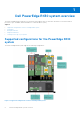
10 Getting help Topics: • • • Contacting Dell EMC Documentation feedback Accessing system information by using QRL Contacting Dell EMC Dell EMC provides several online and telephone based support and service options. If you do not have an active internet connection, you can find contact information about your purchase invoice, packing slip, bill, or Dell EMC product catalog. Availability varies by country and product, and some services may not be available in your area.
Steps 1. Go to www.dell.com/qrl and navigate to your specific product or 2. Use your smartphone or tablet to scan the model-specific Quick Resource (QR) code on your system or in the Quick Resource Locator section. Quick Resource Locator for the PowerEdge R430 system Figure 102.