PowerEdge R515 Technical Guide The PowerEdge R515 offers enterprise-class features and superior price for performance.
Dell This document is for informational purposes only. Dell reserves the right to make changes without further notice to any products herein. The content provided is as is and without express or implied warranties of any kind. Dell, PowerEdge, OpenManage, and ReadyRails are trademarks of Dell, Inc. Citrix® and XenServer™ are trademarks of Citrix Systems, Inc. and/or one or more of its subsidiaries, and may be registered in the United States Patent and Trademark Office and in other countries.
Dell Table of Contents 1 2 3 4 5 Product Comparison ........................................................................................... 7 1.1 Overview .................................................................................................. 7 1.1.1 Designed to Go the Distance...................................................................... 7 1.1.2 Efficient from the Inside Out ..................................................................... 7 1.1.3 Easy to Manage ............
Dell 5.3 Supported Processors .................................................................................. 5.4 Processor Configurations .............................................................................. 5.5 Processor Installation .................................................................................. 6 Memory ........................................................................................................ 6.1 Overview ......................................................
Dell 15.1 Overview/Description ................................................................................. 15.2 Server Management .................................................................................... 15.3 Embedded Server Management ...................................................................... 15.4 Lifecycle Controller and Unified Server Configurator ............................................ 15.5 iDRAC Express...................................................................
Dell Figures Figure Figure Figure Figure Figure Figure Figure Figure Figure Figure Figure Figure Figure Figure Figure Figure Figure Figure 1. 2. 3. 4. 5. 6. 7. 8. 9. 10. 11. 12. 13. 14. 15. 16. 17. 18. R515 Chassis Dimensions ........................................................................... Front View (8 Hard Drive Chassis) ................................................................ Front View (12 Hard Drive Chassis) ...............................................................
Dell 1 Product Comparison 1.1 Overview The Dell™ PowerEdge™ R515 is a 2-socket 2U rack server well-suited for database, email, virtualization, workload consolidation, and other applications requiring an immense amount of local storage.
Dell The optional Lifecycle Controller helps you perform system diagnostics, hardware configuration, and system deployment in a pre-operating-system environment from an easy-to-use interface called the Unified Server Configurator (USC). This helps eliminate the need to use and maintain multiple pieces of CD/DVD media and helps get your server up and running fast. An interactive LCD screen (8 hard drive model) on the front of the server allows for easy setup, monitoring, and maintenance.
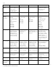
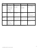
Dell Feature R510 R515 (8 HDD) R515 (12 HDD) R710 Ext Drive Bay(s) 1 for slim optical drive in 4-HDD and 8-HDD chassis No optical drive in 12-HDD chassis 1 for slim optical drive No optical drive Optional flex bay expansion to support half-height tape backup unit Embedded HD Controller Chipset-based SATA Chipset-based SATA Chipset-based SATA Chipset-based SATA Optional Storage Controller Non-RAID: SAS 5/E LSI 2032 (for tape backup unit only) RAID: SAS 6/iR Modular PERC 6/i PERC 6/E PERC H200
Dell Feature R510 R515 (8 HDD) R515 (12 HDD) R710 Power Supplies 4-HDD chassis: non-redundant, 480W (80+ SILVER) 8-HDD and 12-HDD chassis: hot-plug redundant 750W (80+ GOLD) Auto ranging (100V~240V) Hot-plug redundant 750W (80+ GOLD) Auto ranging (100V~240V) Hot-plug redundant 750W (80+ GOLD) Auto ranging (100V~240V) Two hot-plug high efficient 570W or Two hot-plug 870W (1+1) Fans Non-redundant, non-hot-pluggable Non-redundant, nonhot-pluggable Redundant, non-hotpluggable 5 hot-plug fans (defa
Dell 2 System Overview Table 2.
Dell Feature Technical Specification Communications Optional add-in NICs: Intel® 10GBase-T Copper Single Port NIC, PCI-E x8 Intel® PRO 1000 PT Single Port Adapter, Gigabit Ethernet NIC, PCIe x1 Intel® Gigabit ET Dual Port Server Adapter, PCIe x4 Intel® Gigabit ET Quad Port Server Adapter, PCIe x4 Intel® Ethernet X520 DA2 Dual-Port 10 Gigabit Server Adapter Intel® X520-T2 Dual-Port 10 Gigabit Ethernet Server Adapter Broadcom® BCM5709C IPV6 Gigabit Copper Dual Port NIC with TOE and iSCSI Offload, PCIe x4 B
Dell Feature Technical Specification Operating Systems Microsoft® Windows® Small Business Server 2008 Microsoft® Windows Server® 2008 SP2, x86/x64 (x64 includes Hyper-V™) Microsoft® Windows Server® 2008 SP2 R2, x64 (includes Hyper-V™ v2) Microsoft® Windows® HPC Server 2008 Novell® SUSE® Linux® Enterprise Server Red Hat® Enterprise Linux® Optional Embedded Hypervisors: Citrix® XenServer® VMware® vSphere™ 4.1 (including VMware ESX® 4.1 or VMware ESXi™ 4.
Dell 3 Mechanical 3.1 Chassis Description PowerEdge R515 chassis is a 2U rack-mount design that supports the following configurations: 8 hard drive chassis: o 8 hot-plug 3.5‖ SAS/SATA hard drives (2.5‖ SAS/SSD with hard drive carrier) o 750W redundant power supplies o 11G diagnostic LCD 12 hard drive chassis: o 12 hot-plug 3.5‖ SAS/SATA and 2 internal cabled 2.5‖ SAS/SATA hard drives o 750W redundant power supplies o Rack-ear diagnostic LED o Redundant system cooling 3.
Dell 3.3 Front Panel View and Features The PowerEdge R515 is available in two chassis configurations: 8 hard drive chassis (see Figure 2) and 12 hard drive chassis (as shown in Figure 3). The 8 hard drive chassis has a configuration including the LCD panel, buttons, and connectors on the front panel. The 12 hard drive chassis has a configuration including the LED panel, connectors, and buttons located on the rack ears above the latches. You cannot upgrade a chassis from one configuration to another.
Dell Figure 5. Back View See the Back-Panel Features and Indicators section in the About Your System chapter of the PowerEdge R515 Hardware Owner’s Manual on Support.Dell.com for more information. 3.5 Power Supply Indicators The PowerEdge R515 redundant power supplies have one status bi-color LED: green for AC power present and amber for a fault as detailed in Table 3. Table 3.
Dell Figure 7. Right Side View 3.8 Rails and Cable Management 3.8.1 ReadyRails Sliding Rails ReadyRailsTM Sliding Rails for 4-post racks support the following: 3.8.
Dell Figure 8. Figure 9. 3.9.2 R515 Mounted in B3 Sliding Rails Back View of R515 Mounted in B3 Sliding Rails with CMA Static Rails The R515 static rails are also a stab-in design, but unlike the sliding rails, they do not include middle (intermediate) rail members. After the inner chassis rail members have been attached to the sides of the chassis, they are inserted directly into the outer cabinet rail members installed in the rack. See Figure 10 for a view of the R515 mounted in B4 static rails.
Dell 3.11 Control Panel/LCD The PowerEdge R515 includes one of the following control panel configurations: LCD panel (8 hard drive chassis only) LED panel (12 hard drive chassis only) 3.11.1 LCD Panel Configuration Figure 11 and Figure 12 show the LCD panel configuration for the PowerEdge R515 with 8 HDDs. Figure 11. LCD Panel Configuration Figure 12. LCD Panel (Detailed View) The LCD panel is located on the front of the system chassis to provide user access to buttons, display, and I/O interfaces.
Dell 3.11.2 LED Panel Configuration Figure 13 and Figure 14 show the LCD panel configuration for the PowerEdge R515 with 12 HDDs. Figure 13. LED Panel Configuration Figure 14. LED Panel (Detailed View) For a complete description of LED indicators, their causes, and possible courses of action to take to resolve an error, see the Diagnostic Lights (Optional) section in the About Your System chapter in the PowerEdge R515 Hardware Owner’s Manual on Support.Dell.com. 3.
Dell 3.12.4 TPM The TPM is used to generate/store keys, protect/authenticate passwords, and create/store digital certificates. TPM can also be used to store the Microsoft® BitLocker™ keys for hard drive encryption features in Microsoft® Windows Server® 2008. TPM is enabled through a BIOS option and uses HMAC-SHA1-160 for binding. In China, the S-TPM (Socket TPM) is used. 3.12.5 Power Off Security The control panel is designed such that the power switch cannot be accidentally activated.
Dell For detailed information on replacing parts for the PowerEdge R515, see the Installing System Components chapter in the PowerEdge R515 Hardware Owner’s Manual on Support.Dell.com. 3.16 User Accessible Jumpers, Sockets, and Connectors See the Jumpers and Connectors chapter in the PowerEdge R515 Hardware Owner’s Manual on Support.Dell.com.
Dell 4 Power, Thermal, Acoustic 4.1 Power Supplies The PowerEdge R515 system is powered by hot-plug redundant 750W power supply units. Power is softswitched, allowing power cycling using a switch on the front of the system enclosure, or through software control (through server management functions). The power system is compatible with industry standards, such as ACPI and Server 2000.
Dell Table 4. 750W Power Supply Specifications AC Power Supply (per power supply) Wattage 750W (optional redundant) Voltage 100–240 VAC, auto ranging, 50–60Hz Maximum inrush current Under typical line conditions and over the entire system ambient operating range, the inrush current may reach 55A per power supply for 10ms or less The R515 Energy Smart 750W Power Supply is certified Gold (80 Plus) and Climate Savers 3. It is certified UL approved and incorporates PFC logic. 4.
Dell Altitude Operating -15.2 to 10,668m (-50 to 35,000ft) Note: For altitudes above 2950 feet, the maximum operating temperature is derated 1°F/550 ft. Storage -15.2 to 10,668m (-50 to 35,000ft) The airborne contaminant level is class G2 or lower as defined by ISA-S71.04-1985. 4.5 ENERGY STAR Compliance ENERGY STAR® qualified configurations can be accessed from the ENERGY STAR Compliance results landing page on Dell.com. 4.
Dell Max. Configuration @ 23 ± 2 °C CPU HDD RAID 2 x AMD 4180 6 core 2.8GHz 8 x 3.5‖ 600GB SAS 15,000 rpm PERC H700 Table 7. DIMM Operating Mode LWA-UL (Bels) LpA (dBA) Prominent Tones Idle 5.4 43 Yes Stressed 5.5 43 Yes 8 x 8GB Acoustical Performance (12 HDD Chassis) Typical Configuration @ 23 ± 2 °C CPU HDD RAID 2 x AMD 4180 6 core 2.6GHz 8 x 3.5‖ 2TB SATA 7,200 rpm PERC H700 DIMM HDD RAID 2 x AMD 4180 6 core 2.8GHz 12 x 3.
Dell 5 Processors 5.1 Overview The PowerEdge R515 utilizes the latest four and six core offerings from AMD’s Opteron 4000 series (C32). 5.
Dell 5.4 Processor Configurations The PowerEdge R515 is a two-socket server that will operate with either a single processor or dual processors. When the R515 is configured with a single processor, the memory controller is embedded in the processor and supports 4 DIMMs (1 GB minimum and a 32 GB maximum). When two processors are installed in the system, it supports a total of 8 DIMMs (2 GB minimum and a 128 GB maximum (with 16 GB DIMMS— available Q1 2011). 5.
Dell 6 Memory 6.1 Overview The PowerEdge R515 utilizes DDR3 memory providing a high-performance, high-speed memory interface capable of low latency response and high throughput.
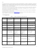
Dell The following is not supported: Mixing of RDIMMs and UDIMMs Use of non-ECC UDIMMs For more information on memory configuration, see the System Memory section in the Installing System Components chapter in the PowerEdge R515 Hardware Owner’s Manual on Support.Dell.com. 6.4 Speed Each processor has 2 DDR3 channels capable of supporting speeds up to 1333 MHz. Single- and dual-rank DIMM types can support speeds up to 1333 MHz. Quad-rank DIMMs can support speeds up to 1066 MHz.
Dell DIMM Slots System Capacity Channel A 1 Socket Channel B UDIMM RDIMM A1 A3 A2 A4 DIMM speed System speed DIMM speed System speed 32GB1 16GB — 16GB — N/A N/A 1066 1066 1 16GB 16GB 16GB 16GB N/A N/A 1066 1066 64GB 1 16 GB DIMMS available Q1 2011 Table 11.
Dell 7 Chipset 7.1 Overview The PowerEdge R515 planar uses a dual IOB configuration using the AMD SR5670 chipset with IO bridges and the SP5100 Southbridge. The SR5670 is designed to support the AMD C32 processor family, HyperTransport-3 Interface (@ 2.6GHz), DDR3 memory technology, and PCI Express Generation 2. The chipset consists of the SR5670 and the SP5100. 7.
Dell 8 BIOS 8.1 Overview The PowerEdge R515 BIOS is based on the Dell BIOS core and supports the following features: AMD C32 processor support Simultaneous Multi-Threading (SMT) support PCI 2.3 compliant Plug and Play 1.0a compliant Multiprocessor (MP) 1.
Dell 8.2 Supported ACPI States The following ACPI states are supported: ACPI compliance: S0, S4, S5 NO S1, S2, S3 (STR) State S4 is supported by the OS only. 8.3 Power Management Modes 8.3.1 Dell Active Power Controller The Dell Active Power Controller (DAPC) is implemented in system BIOS and uses hardware level counters, etc., to determine hardware utilization. The BIOS uses this information to determine when to change the processor’s operating frequency.
Dell Feature Type Enable/Status/ Ctrl bit location Description Power Button Fixed PCH In ACPI mode, OS has control of the power button. In nonACPI mode, SMI handler owns power button events. Real-Time Clock Fixed PCH The OS is able to configure the system to wake on the RTC alarm. Power Mgmt. Timer Fixed PCH 24-bit power management timer is used. Power Mgmt. Event (PME) Generic PCH Each host bus’s PME# signal is routed to a separate generalpurpose event pin in the chipset.
Dell Profile Description Custom CPU Power and Performance Management: Maximum Performance, Minimum Power, OS DBPM, System DBPM Memory Power and Performance Management: Maximum Performance, 1333MHz, 1067MHz, 800MHz, Minimum Power Fan Algorithm: Maximum Performance, Minimum Power 36 PowerEdge R515 Technical Guide
Dell 9 Embedded NICs/LAN on Motherboard (LOM) The Broadcom® 5716 LOM chip is located on the PowerEdge R515 motherboard. The 5716 chip is connected to the IOH via a PCI Express x4 gen2 link. The chip provides two 1xGB Ethernet ports with two RJ-45 connectors on the back of the system. The firmware for the LOM chip resides in a flash part. The PowerEdge R515 supports Wake-On-LAN (WOL) from either port.
Dell 10 I/O Slots 10.1 Overview The PowerEdge R515 includes a total of three PCIe slots and one dedicated internal storage card slot. Two additional PCIe slots are available with the optional Riser 2. All slots are PCI Express Gen 2. See Table 14 and Table 14 for more information. 10.1.1 Riser 1 PCI Expansion Slots Riser 1 includes three PCIe expansion slots and one dedicated slot for an internal storage card. See Table 14. Table 14.
Dell 10.4 PCI Card Dimensions For information about PCIe slots and card dimensions, see the Back-Panel Features and Indicators section in the About Your System chapter in the PowerEdge R515 Hardware Owner’s Manual on Support.Dell.com.
Dell 11 Storage 11.1 Overview There are two chassis types for the PowerEdge R515: 8 hard drive chassis: 8 x hot- plug 3.5‖ or 2.5‖ HDD (in HDD carrier); support for one slim optical disk drive (ODD) 12 hard drive chassis: 12 x hot- plug 3.5‖ or 2.5‖ HDD (in HDD carrier) and 2 x internal cabled 2.5‖ HDD; no ODD support Table 16. Supported Hard Drives Form Factor Capacity Speed Type 3.5‖ 160GB, 250GB, 500GB, 1TB, 2TB 7.2K SATA 3.5‖ 500GB, 1TB, 2TB 7.2K NL SAS 3.5‖ 146GB 15K SAS 3Gb 3.
Dell Mixed HDD (SAS + SATA) Factory Configuration Type Mix HDD (Add-in card) Mixed SAS + SATA (must be all 3.5" HDDs) (ex. Min 2 x SAS + 2 x SATA; max 2 x SAS + 6 x SATA) # Name Description Min HDD Max HDD C10 ASS-X No RAID (PERC H200) 2+ 2 2+ 6 C11 ASSR1/R5X RAID1 + RAID5 (PERC H700) 3+ 3 2+ 6 Mixed HDD (SSD + SAS) Factory Configuration Mixed SSD + SAS (must be all 2.5" HDDs) (ex.
Dell Table 19. RAID Configurations (12 HDD Chassis, 12 + 2 HDDs) (12 + 2 HDD) Factory Configuration No Mixed HDD (Must be all 2.5" or 3.
Dell by the disk drive during normal operation. The bicolor LED is controlled by the SEP device on the backplane. Both LEDs are used to indicate certain conditions under direction of a storage controller. For more information, see the Hard-Drive Indicator Patterns section in the About Your System chapter in the PowerEdge R515 Hardware Owner’s Manual on Support.Dell.com. 11.6 Optical Drives The PowerEdge R515 supports one SATA interface, DVD-ROM or DVD+/-RW, in the 8 hard drive chassis.
Dell 12 Video The PowerEdge R515 is equipped with a Matrox® G200eW with 8MB memory integrated in the Nuvoton® WPCM450 (BMC controller). The resolutions supported are listed in Table 20. Table 20.
Dell 13 Rack Information 13.1 Overview The ReadyRails™ sliding and static rail systems for the R515 provide toolless support for 4-post racks with square or unthreaded round mounting holes including all generations of Dell racks. Both support tooled mounting in 4-post threaded racks (an optional adapter brackets kit is required for the sliding rails), with the static rails also providing tooled mounting support for 2-post (Telco) racks for added versatility.
Dell The adapter brackets kit includes 6 brackets to accommodate different rail lengths, plus four sets of custom screws in common thread sizes. See Figure 17. A detailed Getting Started Guide is included in the kit along with directions for installing the brackets and mounting the rails into the brackets. Depending on the depth of the rack used, it may be necessary to remove the server’s bezel in order to close the door of the rack.
Dell One key factor in selecting the proper rails is identifying the type of rack in which they will be installed. Both the sliding rails and the static rails support mounting in 19‖-wide, EIA-310-E compliant 4-post racks, but only the static rails, as the more generic or universal solution, support mounting in 2-post (Telco) racks. Table 21 provides a summary of the rack types supported by the R515 rails. Table 21.
Dell Hook-and-loop straps are utilized (rather than plastic tie wraps) to eliminate the risk of cable damage during cycling. A low-profile fixed tray is included to support and retain the CMA in its fully-closed position. The CMA and the tray can be mounted without the use of tools using simple and intuitive snap-in designs.
Dell 14 Operating Systems and Virtualization For detailed information, see the following: • • Operating System Support Matrix for Dell PowerEdge Systems on www.Dell.com. Dell PowerEdge R515 Systems Getting Started With Your System guide on Support.Dell.com.
Dell 15 Systems Management 15.1 Overview/Description Dell aims on delivering open, flexible, and integrated solutions that help you reduce the complexity of managing disparate IT assets by building comprehensive IT management solutions. Combining Dell PowerEdge Servers with a wide selection of Dell-developed management solutions gives you choice and flexibility, so you can simplify and save in environments of any size.
Dell Remote Access Controller) is responsible for acting as an interface between the host system and its management software and the periphery devices. These periphery devices consist of the PSUs, the storage backplane, integrated SAS HBA or PERC 6/I, and control panel with display. The optional upgrade to iDRAC6 provides features for managing the server remotely or in data center lightsout environments. Advanced iDRAC features require the installation of the optional iDRAC6 Enterprise card. 15.
Dell • • • Server Sensor monitoring and fault alerting Secure operation of remote access functions including authentication, authorization, and encryption Power control and management with the ability to limit server power consumption and remotely control server power states • Advanced troubleshooting capabilities For more information on iDRAC6 Express features see Table 24. 15.6 iDRAC6 Enterprise The optional iDRAC6 Enterprise card provides access to advanced iDRAC6 features.
Dell Feature BMC iDRAC6 Express iDRAC6 Enterprise vFlash Media Security and Authentication Role-based Authority Local Users Active Directory SSL Encryption Remote Management and Remediation Remote Firmware Update Server power control Serial-over-LAN (with proxy) Serial-over-LAN (no proxy) Power capping Last crash screen capture Boot capture Serial-over-LAN Virtual media
Dell 16 USB Peripherals The PowerEdge R515 supports the following USB devices: USB key (bootable) Keyboard (only one USB keyboard is supported) Mouse (only one USB mouse is supported) Optional USB DVD-ROM 54 PowerEdge R515 Technical Guide
Dell Appendix A. Statement of Volatility The Dell PowerEdge R515 contains both volatile and non-volatile (NV) components. Volatile components lose their data immediately upon removal of power from the component. Non-volatile components continue to retain their data even after the power has been removed from the component. Components chosen as userdefinable configuration options (those not soldered to the motherboard) are not included in the Statement of Volatility.
Dell LOM (LAN [Network Interface] on Motherboard) Memory Details Size: 4Mb (1MB) Type: [e.g., Flash PROM, EEPROM]: Flash Can user programs or operating system write data to it during normal operation? Yes, under software control. Purpose? [e.g., boot code] Contains LOM boot code and config data How is data input to this memory? Requires vendor provided firmware file and loader program used during factory assembly or possible field update.
Dell TPM (Trusted Platform Module; Details For boards shipped outside of China; Boards sold to destinations in China do not have TPM at this time) Size: Unspecified size of user ROM, RAM, EEPROM; 128 bytes of OTP memory included Type: [e.g., Flash PROM, EEPROM]: ROM, RAM, EEPROM Can user programs or operating system write data to it during normal operation? Yes, operating systems and applications that conform to the TCG standard can write data to the TPM during normal operation.
Dell Embedded Bootable Memory Device Details Size: 1GB Type: [e.g., Flash PROM, EEPROM]: MMC Can user programs or operating system write data to it during normal operation? Yes Purpose? [e.g., boot code] Optional embedded boot device How is data input to this memory? Factory installed or via USB bus How is this memory write protected? Not write protected Server BMC (Baseboard Management Controller) Firmware Flash Memory Details Size: 16MB Flash Type: [e.g.
Dell Appendix B. Certifications B.1 Regulatory Certifications Regulatory models: E12S (8 HDD chassis) E13S (12 HDD chassis) Regulatory types: E12S002 (8 HDD chassis) E13S002 (12 HDD chassis) Regulatory compliance information can be located at the following sites: Product Safety, EMC and Environmental Datasheets Dell Regulatory Compliance Home Page B.
Dell Country/Region Authority or Mark Ukraine UKRTEST or UKRSERTCOMPUTER United States NRTL Uzbekistan STZ B.3 Electromagnetic Compatibility The product has been certified and bears the Mark, as applicable, of the EMC authorities as indicated in Table 27. Table 27.
Dell B.4 Ergonomics, Acoustics and Hygienics The product has been certified and bears the Mark, as applicable, of the Ergonomics, Acoustics, and Hygienics authorities as indicated in Table 28. Table 28.
Dell Appendix C. Additional Information and Options The PowerEdge R515 system conforms to the industry standards detailed in Table 29. Table 29. Industry Standards Standard URL for information and specifications ACPI Advance Configuration and Power Interface Specification, v2.0c http://www.acpi.info/ Energy Star EPA Version 1.0 of the Computer Server specification http://www.energystar.gov/index.cfm?c=archives.enterprise _servers Ethernet IEEE 802.3-2005 http://standards.ieee.org/getieee802/802.
Dell Standard URL for information and specifications UEFI Unified Extensible Firmware Interface Specification, v2.1 http://www.uefi.org/specs/ USB Universal Serial Bus Specification, Rev. 2.0 http://www.usb.org/developers/docs/ Windows Logo Windows Logo Program System and Device Requirements, v3.10 http://www.microsoft.com/whdc/winlogo/hwrequirements.