Dell PowerEdge R920 System Owner's Manual Regulatory Model: E23S Series Regulatory Type: E23S001
Notes, Cautions, and Warnings NOTE: A NOTE indicates important information that helps you make better use of your computer. CAUTION: A CAUTION indicates either potential damage to hardware or loss of data and tells you how to avoid the problem. WARNING: A WARNING indicates a potential for property damage, personal injury, or death. Copyright © 2014 Dell Inc. All rights reserved. This product is protected by U.S. and international copyright and intellectual property laws.
Contents 1 About Your System......................................................................................................................9 Front-Panel Features And Indicators....................................................................................................................... 9 LCD Panel Features.................................................................................................................................................10 Home Screen..............................
Using The Boot Manager Navigation Keys...................................................................................................... 31 Boot Manager Screen......................................................................................................................................31 UEFI Boot menu................................................................................................................................................31 Embedded System Management.........................
Installing A 2.5 Inch Hard-Drive Blank............................................................................................................. 56 Removing A Hot-Swap Hard Drive................................................................................................................... 57 Installing A Hot-Swap Hard Drive.................................................................................................................... 57 Removing A Hard Drive From A Hard-Drive Carrier.............
Processors..............................................................................................................................................................83 Removing A Heat Sink Blank ...........................................................................................................................83 Installing A Heat Sink Blank............................................................................................................................. 84 Removing A Processor...........
Troubleshooting A Serial I/O Device.................................................................................................................... 117 Troubleshooting A Wet System............................................................................................................................ 117 Troubleshooting A Damaged System................................................................................................................... 118 Troubleshooting The System Battery.............
Documentation feedback.....................................................................................................................................
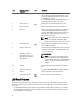
1 About Your System Front-Panel Features And Indicators Figure 1. Front-Panel Features and Indicators Item Indicator, Button, or Connector 1 Power-on indicator, power button Icon Description The power-on indicator lights when the system power is on. The power button controls the power supply output to the system. NOTE: On ACPI-compliant operating systems, turning off the system using the power button causes the system to perform a graceful shutdown before power to the system is turned off.
Item Indicator, Button, or Connector Icon Description Press to toggle the system ID on and off. If the system stops responding during POST, press and hold the system ID button for more than five seconds to enter BIOS progress mode. To reset iDRAC (if not disabled in F2 iDRAC setup), press and hold the button for more than 15 seconds. 4 Video connector Allows you to connect a VGA display to the system. 5 LCD menu buttons Allows you to navigate the control panel LCD menu.
• The LCD backlight remains off if LCD messaging is turned off through the iDRAC utility, the LCD panel, or other tools. Figure 2. LCD Panel Features Item Button Description 1 Left Moves the cursor back in one-step increments. 2 Select Selects the menu item highlighted by the cursor. 3 Right Moves the cursor forward in one-step increments.
Option Description Set error Select SEL to display LCD error messages in a format that matches the IPMI description in the SEL. This is useful when trying to match an LCD message with an SEL entry. Select Simple to display LCD error messages in a simplified user-friendly description. See System Error Messages for a list of messages in this format. Set home Select the default information to be displayed on the LCD Home screen.
Drive-Status Indicator Pattern (RAID Only) Condition Blinks green two times per second Identifying drive or preparing for removal Off Drive ready for insertion or removal NOTE: The drive status indicator remains off until all hard drives are initialized after the system is turned on. Drives are not ready for insertion or removal during this time.
State Name Slot/Device State Status LED (Green) Status LED (Amber) Device identify (blink) The device is identifying the On for 250 msec slot location or is indicating Off for 250 msec the device has received a Prepare for Removal command from the host operating system. Off Device failed The host operating system Off no longer has access to the device because the device is not responding or has encountered a critical error condition.
Item Indicator, Button, or Connector Icon Description 4 Serial connector Allows you to connect a serial device to the system. 5 USB connectors (2) Allows you to connect USB devices to the system. The ports are USB 2.0-compliant. 6 PCIe expansion card slots (8 or 10 depending on the I/O risers installed) Allows you to connect PCI Express expansion cards.
Indicator Indicator Code Link and activity indicators are off The NIC is not connected to the network. Link indicator is green The NIC is connected to a valid network at its maximum port speed (1 Gbps or 10 Gbps). Link indicator is amber The NIC is connected to a valid network at less than its maximum port speed. Activity indicator is blinking green Network data is being sent or received.
Power Indicator Pattern Condition Not lit Power is not connected. Green The handle/LED indicator lights green indicating that a valid power source is connected to the power supply and that the power supply is operational. Flashing amber Indicates a problem with the power supply. CAUTION: When correcting a power supply mismatch, replace only the power supply with the flashing indicator.
• For more information on the system and how-to videos, scan the Quick Resource Locator (QRL) available on your system. NOTE: Download the QRL application from your mobile platform to enable the application on your mobile device. • Always check for updates on dell.com/support/manuals and read the updates first because they often supersede information in other documents. Quick Resource Locator Use the Quick Resource Locator (QRL) to get immediate access to system information and how-to videos.
Using The System Setup and Boot Manager 2 System Setup enables you to manage your system hardware and specify BIOS-level options. The following keystrokes provide access to system features during startup: Keystroke Description Opens the System Setup page. Enters System Services and starts Lifecycle Controller, which supports systems management features such as operating system deployment, hardware diagnostics, firmware updates, and platform configuration, using a graphical user interface.
• UEFI boot mode is an enhanced 64-bit boot interface based on Unified Extensible Firmware Interface (UEFI) specifications that overlays the system BIOS. You must select the boot mode in the Boot Mode field of the Boot Settings screen of System Setup. Once you specify the boot mode, the system boots in the specified boot mode and you then proceed to install your operating system from that mode.
System Setup Options System Setup Main Screen NOTE: Press to reset the BIOS or UEFI settings to their default settings. Menu Item Description System BIOS This option is used to view and configure BIOS settings. iDRAC Settings This option is used to view and configure iDRAC settings. Device Settings This option is used to view and configure device settings. System BIOS Screen NOTE: The options for System Setup change based on the system configuration.
Menu Item Description System BIOS Version Displays the BIOS version installed on the system. System Service Tag Displays the system Service Tag. System Manufacturer Displays the name of the system manufacturer. System Manufacturer Displays the contact information of the system manufacturer. Contact Information Memory Settings Screen Menu Item Description System Memory Size Displays the amount of memory installed in the system. System Memory Type Displays the type of memory installed in the system.
Menu Item Description Adjacent Cache Line Prefetch Allows you to optimize the system for applications that require high utilization of sequential memory access. By default, the Adjacent Cache Line Prefetch option is set to Enabled. You can disable this option for applications that require high utilization of random memory access. Hardware Prefetcher Allows you to enable or disable hardware prefetcher. By default, the Hardware Prefetcher option is set to Enabled.
Boot Settings Screen Menu Item Description Boot Mode Allows you to set the boot mode of the system. CAUTION: Switching the boot mode may prevent the system from booting if the operating system is not installed in the same boot mode. If the operating system supports UEFI, you can set this option to UEFI. Setting this field to BIOS allows compatibility with non-UEFI operating systems. By default, the Boot Mode option is set to BIOS. NOTE: Setting this field to UEFI disables BIOS Boot Settings menu.
Menu Item Description NOTE: This option is displayed only if IDSDM is installed on the system board. Integrated Network Card 1 Allows you to enable or disable the integrated network card 1. By default, the Integrated Network Card 1 option is set to Enabled. OS Watchdog Timer Allows you to enable or disable the OS watchdog timer. When this field is enabled, the operating system initializes the timer and the OS watchdog timer helps in recovering the operating system.
Menu Item Description Redirection After Boot Allows you to enable or disable to the BIOS console redirection when the operating system is loaded. By default, the Redirection After Boot option is set to Enabled. System Profile Settings Screen Menu Item Description System Profile Allows you to set the system profile. If you set the System Profile option to a mode other than Custom, the BIOS automatically sets the rest of the options.
System Security Screen Menu Item Description Intel AES-NI The Intel AES-NI option improves the speed of applications by performing encryption and decryption using the Advanced Encryption Standard Instruction Set and is set to Enabled by default. System Password Allows you to set the system password. This option is read-only if the password jumper is not installed in the system. Setup Password Allows you to set the setup password.
Miscellaneous Settings Menu Item Description System Time Allows you to set the time on the system. System Date Allows you to set the date on the system. Asset Tag Displays the asset tag and allows you to modify it for security and tracking purposes. Keyboard NumLock Allows you to set whether the system boots with the NumLock enabled or disabled. By default the Keyboard NumLock is set to On. NOTE: This option does not apply to 84-key keyboards.
To assign a system and/or setup password: 1. To enter System Setup, press immediately after a power-on or reboot. 2. In the System Setup Main Menu, select System BIOS and press . The System BIOS screen is displayed. 3. In the System BIOS screen, select System Security and press . The System Security screen is displayed. 4. In the System Security screen, verify that Password Status is Unlocked. 5. Select System Password , enter your system password, and press or .
Using Your System Password To Secure Your System NOTE: If you have assigned a setup password, the system accepts your setup password as an alternate system password. 1. Turn on or reboot your system. 2. Type your password and press . When Password Status is Locked, type the password and press when prompted at reboot. If an incorrect system password is entered, the system displays a message and prompts you to re-enter your password. You have three attempts to enter the correct password.
Using The Boot Manager Navigation Keys Key Description Up arrow Moves to the previous field. Down arrow Moves to the next field. Allows you to type in a value in the selected field (if applicable) or follow the link in the field. Spacebar Expands or collapses a drop-down list, if applicable. Moves to the next focus area. NOTE: For the standard graphics browser only. Moves to the previous page till you view the main screen.
Menu Item Description Add Boot Option Adds a new boot option. Delete Boot Option Deletes an existing boot option. Boot From File Sets a one-time boot option not included in the boot option list. Embedded System Management The Dell Lifecycle Controller provides advanced embedded systems management throughout the server’s lifecycle. The Lifecycle Controller can be started during the boot sequence and can function independently of the operating system.
Installing System Components 3 Recommended Tools You may need the following items to perform the procedures in this section: • Key to the system keylock • #2 Phillips screwdriver • 10 in-lb.
Figure 9. Removing and Installing the Front Bezel 1. release latch 3. locking hooks 2. front bezel Installing The Front Bezel 1. Hook the right end of the bezel onto the chassis. 2. Fit the free end of the bezel onto the chassis. 3. Secure the bezel with the keylock. Opening And Closing The System WARNING: Whenever you need to lift the system, get others to assist you. To avoid injury, do not attempt to lift the system by yourself.
Opening The System NOTE: It is recommended that you always use a static mat and static strap while working on components inside the system. 1. Turn off the system and attached peripherals, and disconnect the system from the electrical outlet. 2. Rotate the latch release lock counter clockwise to the unlocked position. 3.
Inside The System CAUTION: Many repairs may only be done by a certified service technician. You should only perform troubleshooting and simple repairs as authorized in your product documentation, or as directed by the online or telephone service and support team. Damage due to servicing that is not authorized by Dell is not covered by your warranty. Read and follow the safety instructions that came with the product.
Chassis Intrusion Switch CAUTION: Many repairs may only be done by a certified service technician. You should only perform troubleshooting and simple repairs as authorized in your product documentation, or as directed by the online or telephone service and support team. Damage due to servicing that is not authorized by Dell is not covered by your warranty. Read and follow the safety instructions that came with the product.
Figure 12. Removing and Installing the Chassis Intrusion Switch 1. chassis intrusion switch 3. chassis intrusion switch cable 2. NDC riser (riser 1) Cable Management Tray The cable management tray is located above the processor heat sinks. It is used to route and manage the cables connecting the storage and expansion cards to various connectors on the backplane. NOTE: Cable management tray also facilitates in maintaining the proper cooling of the system.
Figure 13. Removing and Installing the Cable Management Tray 1. cable tray slot (4) 2. cable tray hook (4) 3. cable tray cover 4. cable tray cover release tab 5. cables (routed) Installing The Cable Management Tray 1. Position the cable management tray above the processor heat sinks. 2. Lower the cable tray and insert the cable tray hooks into the slots on one side of the chassis. 3. Press the hooks so that they snap into the slots on the other side of the chassis. 4.
Memory bus operating frequency can be 1066 MT/s, 1333 MT/s, and 1600 MT/s depending on: • DIMM type (RDIMM and LRDIMM) • DIMM configuration (number of ranks) • Maximum frequency of the DIMMs • Number of DIMMs populated per channel • DIMM operating voltage • System profile selected (for example, Performance Optimized, Custom, or Dense Configuration Optimized) • Maximum supported DIMM frequency of the processors The system memory contain 96 memory sockets organized into eight memory risers, spli
Figure 14.
channel 2: slots E3, E7, and E11 channel 3: slots E4, E8, and E12 channel 0: slots F1, F5, and F9 channel 1: slots F2, F6, and F10 channel 2: slots F3, F7, and F11 channel 3: slots F4, F8, and F12 Processor 4 channel 0: slots G1, G5, and G9 channel 1: slots G2, G6, and G10 channel 2: slots G3, G7, and G11 channel 3: slots G4, G8, and G12 channel 0: slots H1, H5, and H9 channel 1: slots H2, H6, and H10 channel 2: slots H3, H7, and H11 channel 3: slots H4, H8, and H12 The following table shows the memory po
DIMM Type DIMMs Populated/ Channel (DPC) DIMM Size Operating Frequency (in MT/s) DDR3 (1.5 V) Maximum DIMM Rank/ Channel DDR3 (1.35 V) 2 32 GB / 64 GB 1600 1333 Quad rank physical 3 32 GB / 64 GB 1333 and 1066 Not Applicable Quad rank physical General Memory Module Installation Guidelines Your system supports Flexible Memory Configuration, enabling the system to be configured and run in any valid chipset architectural configuration.
• Memory modules must be identical in size, speed, and technology. • DIMMs installed in memory sockets with white release tabs must be identical and similar rule applies for sockets with black and green release tabs. This ensures that identical DIMMs are installed in matched pairs - for example, A1 with A2, A3 with A4, A5 with A6, and so on. NOTE: Advanced ECC with Mirroring is supported.
NOTE: DIMMs populated must be identical for each riser. In the mirroring mode, only one of the two CPUs is populated. NOTE: 64GB LRDIMMs are supported by the system. Table 2.
Memory Mode Mirroring and Partial Mirroring 46 System Capacity (in GB) DIMM Size (in GB) Number of DIMMs 128 16 8 X 96 16 6 X 128 16 8 X 192 32 6 X 256 32 8 X 192 32 6 X 256 32 8 X 384 32 12 X 384 64 6 X 512 64 8 X 768 64 12 X 1024 64 16 1536 64 32 DIMM Slot Population for CPU 1 ( Riser A and B) X X X X X X X X X X X X X X X X X X X X X X X X X X X X X X X X X X X X X X X X X 24 X X X X X X 4 8 X 64 4
Removing A Memory-Riser Blank CAUTION: Many repairs may only be done by a certified service technician. You should only perform troubleshooting and simple repairs as authorized in your product documentation, or as directed by the online or telephone service and support team. Damage due to servicing that is not authorized by Dell is not covered by your warranty. Read and follow the safety instructions that came with the product. 1.
Installing A Memory-Riser Blank CAUTION: Many repairs may only be done by a certified service technician. You should only perform troubleshooting and simple repairs as authorized in your product documentation, or as directed by the online or telephone service and support team. Damage due to servicing that is not authorized by Dell is not covered by your warranty. Read and follow the safety instructions that came with the product. 1. Align the memory-riser blank with the guides on the memory riser cage. 2.
Figure 16. Removing and Installing the Memory Riser 1. memory riser handle 3. memory riser guide 2. memory riser handle lock Installing A Memory Riser 1. Turn off the system, including any attached peripherals, and disconnect the system from the electrical outlet. 2. Open the system. 3. If applicable, remove the memory-riser blank and orange protective cap on the memory riser connector.
6. Press the handle down by pushing on the blue touch points and sliding the handle lock until it clicks into the locked position. NOTE: If the memory riser is not aligned with the riser guide, the memory riser will not slide smoothly into the slot. If the memory riser handle does not move down, check if the memory riser is properly seated in the memory-riser guide. The handle gets locked only when the memory riser is seated in the connector. 7. Close the system. 8.
Figure 17. Opening and Closing the Memory Riser 1. memory riser release tabs 3. memory riser handle 2. memory riser cover 5. Locate the appropriate memory-module socket(s). 6. To release the memory-module blank from the socket, simultaneously press the ejectors on both ends of the memory module socket. CAUTION: Handle each memory module only by the card edges, making sure not to touch the middle of the memory module or metallic contacts.
Figure 18. Ejecting The Memory Module 7. 1. memory module 3. memory-module socket 2. memory-module socket ejectors (2) If a memory module or a memory-module blank is installed in the socket, remove it. NOTE: Retain the removed memory-module blank(s) for future use. Figure 19. Removing The Memory Module 1. memory module/memory-module blank 8. Install memory-module blanks in vacant memory-module socket(s) to ensure proper system cooling.. 9. Close the memory riser cover. 10.
CAUTION: To ensure proper system cooling, memory-module blanks must be installed in any memory socket that is not occupied. Remove memory-module blanks only if you intend to install memory modules in those sockets. 1. Turn off the system, including any attached peripherals, and disconnect the system from the electrical outlet. 2. Open the system. 3. Locate and remove the memory riser. 4. Push the DIMM release tabs on the memory riser and lift the memory riser cover in the direction of the arrows. 5.
13. Reconnect the system to its electrical outlet and turn on the system, including any attached peripherals. 14. Press to enter the System Setup, and check the memory settings. The system should have already changed the value to reflect the newly installed memory. 15. If the value is incorrect, one or more of the memory modules may not be installed properly. Repeat step 5 through step 8 of this procedure, checking to ensure that the memory modules are firmly seated in their sockets. 16.
Figure 21. Removing and Installing the Memory Riser and Fan Cage 1. memory riser and fan cage handle 2. fan cage 3. memory riser and fan cage back handle 4. handle lock 5. cage guides on the side of the chassis Installing The Memory Riser And Fan Cage NOTE: Before installing the memory riser and fan cage, ensure there are no loose cables from the hard-drive backplane. If the cables are not latched, the cage will not seat firmly into the chassis. 1.
6. Install cooling fans. 7. Close the system. 8. Reconnect the system to its electrical outlet and turn the system on, including any attached peripherals. Hard Drives All hard drives connect to the system board through the hard-drive backplane. Hard drives are supplied in hotswappable hard-drive carriers that fit in the hard-drive slots.
Removing A Hot-Swap Hard Drive CAUTION: To prevent data loss, ensure that your operating system supports hot-swap drive installation. See the documentation supplied with your operating system. 1. From the management software, prepare the hard drive for removal. Wait until the indicators on the hard-drive carrier signal that the hard drive can be removed safely. For more information, see the documentation for the storage controller.
CAUTION: To prevent data loss, ensure that your operating system supports hot-swap drive installation. See the documentation supplied with your operating system. CAUTION: When a replacement hot-swappable hard drive is installed and the system is powered on, the hard drive automatically begins to rebuild. Make absolutely sure that the replacement hard drive is blank or contains data that you wish to have over-written.
Installing A Hard Drive Into A Hard-Drive Carrier CAUTION: Many repairs may only be done by a certified service technician. You should only perform troubleshooting and simple repairs as authorized in your product documentation, or as directed by the online or telephone service and support team. Damage due to servicing that is not authorized by Dell is not covered by your warranty. Read and follow the safety instructions that came with the product. 1.
Figure 25. Removing and Installing the Optical Drive 1. ejector-handle button 3. ejector handle 2. optical drive sled Installing The Optical Drive CAUTION: Many repairs may only be done by a certified service technician. You should only perform troubleshooting and simple repairs as authorized in your product documentation, or as directed by the online or telephone service and support team. Damage due to servicing that is not authorized by Dell is not covered by your warranty.
WARNING: Do not place any physical obstructions in the front or rear of the chassis. This may cause a decrease in airflow, resulting in an over-heating condition. Removing A Cooling Fan WARNING: Opening or removing the system cover when the system is on may expose you to a risk of electric shock. Exercise utmost care while removing or installing cooling fans. WARNING: Do not operate the system without the cooling fans or the cover. CAUTION: Many repairs may only be done by a certified service technician.
Installing A Cooling Fan CAUTION: Many repairs may only be done by a certified service technician. You should only perform troubleshooting and simple repairs as authorized in your product documentation, or as directed by the online or telephone service and support team. Damage due to servicing that is not authorized by Dell is not covered by your warranty. Read and follow the safety instructions that came with the product. 1.
Figure 27. Removing and Installing the Fan Tray 1. fan tray connector 2. fan tray Installing The Fan tray 1. Align the fan tray with the connector and the screw holes on the system board. 2. Lower the fan tray and ensure that the fan tray connector engages with the connector on the system board. 3. Using a #2 Phillips screwdriver, tighten the fan tray screws (2 screws on the left and 1 screw on the right side) to the system board. 4. Install the memory riser and fan cage. 5.
Replacing The Internal USB Key CAUTION: Many repairs may only be done by a certified service technician. You should only perform troubleshooting and simple repairs as authorized in your product documentation, or as directed by the online or telephone service and support team. Damage due to servicing that is not authorized by Dell is not covered by your warranty. Read and follow the safety instructions that came with the product. 1.
Expansion Card Installation Guidelines Your system supports third Generation 10 PCIe expansion card slots that include one dedicated slot for PERC 9 storage card and one dedicated riser-slot for Network Daughter Card (NDC). Slot 1 connector functions as an x8 connector and can be extended as two x4 slots when the left I/O riser is installed. Slot 9 connector functions as an x16 connector and can be extended as two x8 slots when the right I/O riser is installed.
Table 4.
To remove the left expansion card riser blank: 1. Turn off the system, including any attached peripherals, and disconnect the system from the electrical outlet. 2. Open the system. 3. Slide the left riser blank to the left pressing on the metal tab. 4. Lift the riser blank up and away from the system. Store the riser blank for future use. Figure 29. Removing and Installing The Left/Right Expansion Card Riser Blank 1. system chassis 2. left riser blank 3. PCI retention rocker 4.
3. Align the left riser blank with the corresponding slot on the back of the chassis. 4. Press down and slide the blank to the right to lock it in place and replace the PCI retention rocker. Removing The Right Expansion Card Riser Blank CAUTION: Many repairs may only be done by a certified service technician. You should only perform troubleshooting and simple repairs as authorized in your product documentation, or as directed by the online or telephone service and support team.
Figure 30. Removing and Installing Expansion-Card Risers 2 and 3 Cage 1. expansion-card riser 2 cage 2. expansion-card riser handle 3. expansion-card riser 3 cage 4. riser panel 5. guide pin 6.
Figure 31. Removing and Installing the Expansion-Card (half-length) from the Expansion-Card Riser 2 70 1. expansion-card connector on the riser 2. expansion-card (half-length) 3. expansion-card latch 4.
Figure 32. Removing and Installing the Expansion-Card (full-length) from the Expansion-Card Riser 2 1. expansion-card connector on the riser 2. expansion-card (full-length) 3. expansion-card latch 4. expansion-card riser cage To enable the installation of full-length expansion card in expansion-card riser 2 or 3, ensure the metal brackets are removed from the back of the memory cage and fan cage.
Figure 33. Removing The Metal Brackets To Install The Full-Length Expansion Cards 1. memory riser and fan cage 3. right metal bracket 2. left metal bracket Figure 34. Removing and Installing the Expansion-Card from the Expansion-Card Riser 3 72 1. expansion-card riser cage 2. expansion-card connector on the riser 3. expansion-card latch 4.
Installing An Expansion Card Into The Expansion-Card Riser 2 and 3 CAUTION: Many repairs may only be done by a certified service technician. You should only perform troubleshooting and simple repairs as authorized in your product documentation, or as directed by the online or telephone service and support team. Damage due to servicing that is not authorized by Dell is not covered by your warranty. Read and follow the safety instructions that came with the product. 1.
6. Press and slide out the NDC riser panel latch. The NDC riser panel is unlocked. 7. Hold the NDC riser and carefully remove it from the connector on the system board. Figure 35. Removing and Installing the NDC Riser 1. NDC 3. NDC riser connector on the system board 2. PCI retention rocker Installing The NDC Riser (I/O Riser 1) CAUTION: Many repairs may only be done by a certified service technician.
5. Close the system. 6. If applicable, reconnect the external cables to the IO card. 7. Reconnect the system to its electrical outlet and turn the system on, including any attached peripherals. Network Daughter Card The Network Daughter Card (NDC) contains the complete NIC subsystem, it replaces the traditional LAN-onMotherboard (LOM) design with the flexible new features, network types, speed and easy to upgrade from 1G to 10G LAN speeds.
Figure 36. Removing and Installing the Network Daughter Card 1. NDC panel 2. I/O riser card 3. NDC connector on the I/O riser card 4. screw (2) 5. network daughter card Installing The Network Daughter Card CAUTION: Many repairs may only be done by a certified service technician. You should only perform troubleshooting and simple repairs as authorized in your product documentation, or as directed by the online or telephone service and support team.
Replacing An SD vFlash Card 1. Locate the vFlash media slot on the system. 2. To remove the SD vFlash card, push inward on the card to release it, and pull the card from the card slot. Figure 37. Removing and Installing the SD vFlash Card 1. 3. SD vFlash card 2. SD vFlash card slot To install the SD vFlash card, with the label side facing up, insert the contact-pin end of the SD card into the card slot on the module. NOTE: The slot is keyed to ensure correct insertion of the card. 4.
Figure 38. Removing and Installing the Internal Dual SD Module 1. connector on the I/O card 3. blue pull tab 2. internal dual SD module Installing The Internal Dual SD Module CAUTION: Many repairs may only be done by a certified service technician. You should only perform troubleshooting and simple repairs as authorized in your product documentation, or as directed by the online or telephone service and support team.
Removing An Internal SD Card CAUTION: Many repairs may only be done by a certified service technician. You should only perform troubleshooting and simple repairs as authorized in your product documentation, or as directed by the online or telephone service and support team. Damage due to servicing that is not authorized by Dell is not covered by your warranty. Read and follow the safety instructions that came with the product. 1.
Installing An Internal SD Card CAUTION: Many repairs may only be done by a certified service technician. You should only perform troubleshooting and simple repairs as authorized in your product documentation, or as directed by the online or telephone service and support team. Damage due to servicing that is not authorized by Dell is not covered by your warranty. Read and follow the safety instructions that came with the product.
9. Close the system. 10. Reconnect the system to its electrical outlet and turn the system on, including any attached peripherals. Figure 40. Removing and Installing the Integrated Storage Controller Card 1. SAS cable connector 2. storage controller card battery 3. storage controller card 4. clamp 5. storage controller card connector on the system board 6.
7. Close the clamp. 8. Install the NDC riser. 9. If applicable, reinstall the left expansion card riser. 10. Close the system. 11. Reconnect the system to its electrical outlet and turn the system on, including any attached peripherals. RAID Battery Removing a RAID Battery CAUTION: Many repairs may only be done by a certified service technician.
Installing The RAID Battery CAUTION: Many repairs may only be done by a certified service technician. You should only perform troubleshooting and simple repairs as authorized in your product documentation, or as directed by the online or telephone service and support team. Damage due to servicing that is not authorized by Dell is not covered by your warranty. Read and follow the safety instructions that came with the product. 1.
5. Press the heat sink release tabs located at the back of the blank. 6. Lift the heat sink blank out of the system. Figure 42. Removing and Installing the Heat Sink Blank 1. heat sink blank 2. processor blank Installing A Heat Sink Blank CAUTION: Many repairs may only be done by a certified service technician. You should only perform troubleshooting and simple repairs as authorized in your product documentation, or as directed by the online or telephone service and support team.
Removing A Processor CAUTION: Many repairs may only be done by a certified service technician. You should only perform troubleshooting and simple repairs as authorized in your product documentation, or as directed by the online or telephone service and support team. Damage due to servicing that is not authorized by Dell is not covered by your warranty. Read and follow the safety instructions that came with the product. 1. Before upgrading your system, download the latest system BIOS version from dell.
Figure 43. Removing and Installing the Processor Heat Sink 1. heat sink 2. retention screws (4) 3. retention sockets (4) 4. processor CAUTION: The processor is held in its socket under strong pressure. Be aware that the release lever can spring up suddenly if not firmly grasped. 12. Position your thumb firmly over the processor socket-release lever near the unlock icon from the locked position by pushing down and out from under the tab. and release the lever 13.
Figure 44. Processor Shield Opening and Closing Lever Sequence 1. processor socket-release lever 2. close-lock symbol 3. processor 4. processor socket-release lever 5. open-lock symbol 14. Rotate the processor shield upward and out of the way. CAUTION: The socket pins are fragile and can be permanently damaged. Be careful not to bend the pins in the socket when removing the processor out of the socket. 15.
Figure 45. Removing and Installing a Processor 1. processor socket-release lever 2. processor 3. processor shield 4. processor socket-release lever 5. notches in processor 6. socket keys 7. pin 1 indicator 8. ZIF socket NOTE: After removing the processor, place it in an antistatic container for reuse, return, or temporary storage. Do not touch the bottom of the processor. Touch only the side edges of the processor.
NOTE: If you are installing two processors, they must be installed in socket CPU1 and CPU2. 1. Turn off the system, including any attached peripherals, and disconnect the system from the electrical outlet. When disconnected from the power source, press and hold the power button for three seconds to fully drain the system of stored power prior to removing the cover. 2. Open the system. WARNING: The heat sink and processor are hot to the touch for some time after the system has been powered down.
Your system supports Up to four 750 W, 1100 W, and 1600 W (when available) AC power supply modules Or Up to four 1100 W DC power supply modules NOTE: You can install only one 1600 W power supply on each side of the system. When two identical power supplies are installed, the power supply configuration is redundant (1 + 1). In redundant mode, power is supplied to the system equally from both power supplies to maximize efficiency.
Figure 46. Removing and Installing an AC Power Supply 1. connector 2. power supply 3. release latch 4. power supply handle Installing An AC Power Supply CAUTION: Many repairs may only be done by a certified service technician. You should only perform troubleshooting and simple repairs as authorized in your product documentation, or as directed by the online or telephone service and support team. Damage due to servicing that is not authorized by Dell is not covered by your warranty.
Wiring Instructions For A DC Power Supply Your system supports up to two –(48–60) V DC power supplies (when available). WARNING: For equipment using –(48–60) V DC power supplies, a qualified electrician must perform all connections to DC power and to safety grounds. Do not attempt connecting to DC power or installing grounds yourself. All electrical wiring must comply with applicable local or national codes and practices.
3. Connect the safety ground wire to the grounding post on the back of the system using a #6-32 nut equipped with a locking washer. Figure 47. Assembling and Connecting the Safety Ground Wire 1. safety ground wire 2. grounding post 3. locking washer 4. spring washer 5. #6-32 nut Assembling The DC Input Power Wires WARNING: For equipment using –(48–60) V DC power supplies, a qualified electrician must perform all connections to DC power and to safety grounds.
Figure 48. Assembling the DC Input Power Wires 1. DC power socket 2. rubber cap 3. captive screws (2) 4. DC power connector 5. wire –48 V 6. wire RTN 7. grounding wire Removing A DC Power Supply WARNING: For equipment using –(48–60) V DC power supplies, a qualified electrician must perform all connections to DC power and to safety grounds. Do not attempt connecting to DC power or installing grounds yourself.
Figure 49. Removing and Installing a DC Power Supply 1. connector 2. power supply 3. power supply status indicator 4. release latch 5. power supply handle Installing A DC Power Supply WARNING: For equipment using –(48–60) V DC power supplies, a qualified electrician must perform all connections to DC power and to safety grounds. Do not attempt connecting to DC power or installing grounds yourself. All electrical wiring must comply with applicable local or national codes and practices.
Removing The Power Supply Blank CAUTION: To ensure proper system cooling, the power supply blank must be installed in the second power supply bay in a non-redundant configuration. Remove the power supply blank only if you are installing a second power supply. 1. Hold the power supply blank and disengage the tabs from the slots on the chassis. 2. Slightly pull down and remove the power supply blank out of the power supply bay. Figure 50. Removing and Installing the Power Supply Blank 1.
Removing The Power Supply Bay CAUTION: Many repairs may only be done by a certified service technician. You should only perform troubleshooting and simple repairs as authorized in your product documentation, or as directed by the online or telephone service and support team. Damage due to servicing that is not authorized by Dell is not covered by your warranty. Read and follow the safety instructions that came with the product. 1.
3. power supply bay (left) 5. finger grips on the power supply bay 4. power supply bay (right) Installing The Power Supply Bay 1. Position the power supply bay to the side of the chassis. 2. Align four slots on the power supply bay with the hooks on the side wall of the chassis. 3. Align the PDB with the connector on the system board. 4.
Figure 52. Removing and Installing the Power Distribution Board 1. screw (3) 2. power distribution board 3. power supply bay (left) 4. power supply bay (right) Installing The Power Distribution Board CAUTION: Many repairs may only be done by a certified service technician. You should only perform troubleshooting and simple repairs as authorized in your product documentation, or as directed by the online or telephone service and support team.
CAUTION: Many repairs may only be done by a certified service technician. You should only perform troubleshooting and simple repairs as authorized in your product documentation, or as directed by the online or telephone service and support team. Damage due to servicing that is not authorized by Dell is not covered by your warranty. Read and follow the safety instructions that came with the product. 1.
• 2.5 inch (x24) SAS/SATA backplane • 2.5 inch (x16) SAS/SATA backplane and 2.5 inch (x8) Dell PowerEdge Express Flash (PCIe SSD) backplane Removing The Hard-Drive Backplane CAUTION: Many repairs may only be done by a certified service technician. You should only perform troubleshooting and simple repairs as authorized in your product documentation, or as directed by the online or telephone service and support team. Damage due to servicing that is not authorized by Dell is not covered by your warranty.
Figure 54. Removing and Installing the 2.5 Inch (x4) SAS/SATA Backplane 1. release tab 2. system board miscellaneous signal cable 3. SAS connector 4. hard drive connector 5. backplane hook (4) 6. backplane power cable 2. hard drive connector Figure 55. 2.5 Inch (x4) SAS/SATA Backplane—Front view 102 1. SAS connector on the backplane 3.
Figure 56. 2.5 Inch (x4) SAS/SATA Backplane—Back view 1. backplane power cable 2. system board miscellaneous signal cable Figure 57. Removing and Installing the 2.5 Inch (x24) SAS/SATA Backplane 1. release tab (2) 2. backplane jumper connector 3. backplane jumper connector for the expander daughter card 4. backplane power cable 5. SAS connector 6. hard drive connector 7. backplane hook (8) 8.
Figure 58. 2.5 Inch (x24) SAS/SATA Backplane—Front view 1. jumper connector 2. hard drive connector 3. SAS connector 4. hard drive connector 5. backplane loops 6. backplane hook (8) 7. backplane jumper connector 2. backplane power connector 2 Figure 59. 2.5 Inch (x24) SAS/SATA Backplane—Back view 104 1. backplane power connector 1 3.
Figure 60. Removing and Installing the 2.5 Inch (x16) SAS/SATA and (x8) PCIe SSD Backplane 1. release tab (2) 2. backplane jumper connector 3. system board miscellaneous signal cable 4. primary PCIe SSD extender mini-SAS HD connector (4) 5. SAS connector 6. secondary PCIe SSD extender mini-SAS HD connector (4) 7. backplane hook (8) 8. backplane power connector Figure 61. 2.5 Inch (x16) SAS/SATA and (x8) PCIe SSD Backplane—Front view 1. hard drive connector 2. SAS connector 3.
5. backplane hook (8) 6. jumper connector to the expander daughter card Figure 62. Cabling—2.5 Inch (x4) SAS/SATA Backplane with PERC 9 106 1. SAS cable connector on the integrated storage controller card 2. integrated storage controller card (PERC 9) 3. system board 4. cable management tray 5. x4 hard drive backplane 6.
Figure 63. Cabling—2.5 Inch (x24) SAS/SATA Backplane with PERC 9 1. SAS (A&B) cable connector on the integrated storage controller card 2. integrated storage controller card (PERC 9) 3. system board 4. cable management tray 5. x24 hard drive backplane 6. SAS B cable connector on the expander daughter card 7. backplane jumper cable connector on the expander daughter card 8. SAS jumper cable connector on the expander daughter card 9. SAS A cable connector on the expander daughter card 10.
Figure 64. Cabling—2.5 Inch (x16) SAS/SATA and (x8) PCIe SSD Backplane (left and right side) 1. SAS (A&B) cable connector on the integrated storage controller card 2. integrated storage controller card 3. system board 4. cable management tray 5. secondary PCIe SSD extender mini-SAS HD connector (A to D) 6. x24 hard-drive backplane 7. SAS B cable connector on the expander daughter card 8. SAS jumper cable connector on the expander daughter card 9.
Figure 65. Cabling— x24 Backplane With Dual PERC And Dual SAS Expander Cards 1. SAS cable connector on the primary integrated storage controller card 2. integrated storage controller card (primary card) 3. integrated storage controller card (secondary card) 4. SAS cable connector on the secondary integrated storage controller card 5. x24 hard drive backplane 6. primary daughter card SAS B connector 7. primary daughter card SAS A connector 8. secondary daughter card SAS B connector 9.
Installing The Hard-Drive Backplane CAUTION: Many repairs may only be done by a certified service technician. You should only perform troubleshooting and simple repairs as authorized in your product documentation, or as directed by the online or telephone service and support team. Damage due to servicing that is not authorized by Dell is not covered by your warranty. Read and follow the safety instructions that came with the product. 1.
6. Pull and remove the SAS expander daughter card sled out of the system chassis. Figure 66. Removing and Installing the SAS Expander Daughter Card 1. SAS expander daughter card sled 2. release tab (2) Installing The SAS Expander Daughter Card 1. Press the two release tabs inwards to release the lock. Once the lock is released, the release tabs pop-up. 2. Align the SAS expander daughter card with the opening on the front-panel of the system. 3.
NOTE: Note the routing of the cables on the side of the system as you remove them from the control panel board. You must route these cables properly when you replace them inside the shim stock pieces to prevent them from being pinched or crimped. 4. Using a Phillips screwdriver, remove the two screws that secure the control panel board to the chassis. 5. Slide the control panel board toward the back of the system and remove. Figure 67. Removing and Installing the Control Panel Board 1.
4. Close the system. 5. Reconnect the system to its electrical outlet and turn the system on, including any attached peripherals. System Board Removing The System Board CAUTION: Many repairs may only be done by a certified service technician. You should only perform troubleshooting and simple repairs as authorized in your product documentation, or as directed by the online or telephone service and support team. Damage due to servicing that is not authorized by Dell is not covered by your warranty.
Figure 68. Removing and Installing the System Board 1. release pin 2. system board Installing The System Board CAUTION: Many repairs may only be done by a certified service technician. You should only perform troubleshooting and simple repairs as authorized in your product documentation, or as directed by the online or telephone service and support team. Damage due to servicing that is not authorized by Dell is not covered by your warranty.
j. k. l. m. n. 5. cooling fans (6) cable management tray SAS backplane internal USB key (if installed) optical drive Reconnect the cables to the system board, hard-drive backplane, control panel board, and the optical drive cable (if applicable). NOTE: Ensure that the cables inside the system are routed along the chassis wall and secured using the shimstock pieces. 6. Close the system. 7. Reconnect the system to its electrical outlet and turn the system on, including any attached peripherals. 8.
Troubleshooting Your System 4 Safety First—For You And Your System CAUTION: Many repairs may only be done by a certified service technician. You should only perform troubleshooting and simple repairs as authorized in your product documentation, or as directed by the online or telephone service and support team. Damage due to servicing that is not authorized by Dell is not covered by your warranty. Read and follow the safety instructions that came with the product.
6. If the problem is not resolved, proceed to the next step to begin troubleshooting the other USB devices attached to the system. 7. Power down all attached USB devices and disconnect them from the system. 8. Reboot the system and, if your keyboard is functioning, enter the System Setup. Verify that all USB ports are enabled on the Integrated Devices screen, in the System Setup options. If your keyboard is not functioning, you can also use remote access.
• Memory riser and fan cage 4. • Processor(s) and heat sink(s) Let the system dry thoroughly for at least 24 hours. 5. Reinstall the components you removed in step 3. 6. Close the system. 7. Turn on the system and attached peripherals. If the system does not start properly, see Getting Help. 8. If the system starts properly, shut down the system and reinstall all of the expansion cards that you removed. 9. Run the appropriate diagnostic test. For more information, see Using System Diagnostics.
Troubleshooting The System Battery CAUTION: Many repairs may only be done by a certified service technician. You should only perform troubleshooting and simple repairs as authorized in your product documentation, or as directed by the online or telephone service and support team. Damage due to servicing that is not authorized by Dell is not covered by your warranty. Read and follow the safety instructions that came with the product.
• The expansion card installation guidelines have not been followed. Troubleshooting Cooling Fans CAUTION: Many repairs may only be done by a certified service technician. You should only perform troubleshooting and simple repairs as authorized in your product documentation, or as directed by the online or telephone service and support team. Damage due to servicing that is not authorized by Dell is not covered by your warranty. Read and follow the safety instructions that came with the product. 1.
14. If a diagnostic test or error message indicates a specific memory module as faulty, swap or replace the module with a known good memory module. 15. Open the system. 16. Remove the memory risers. 17. To troubleshoot an unspecified faulty memory module, replace the memory module in the first DIMM socket with a module of the same type and capacity. If an error message is displayed on the screen, this may indicate a problem with the installed DIMM type(s), incorrect DIMM installation, or defective DIMM(s).
CAUTION: If the Internal SD Card Redundancy option is set to Mirror Mode in the Integrated Devices screen of the System Setup, you must follow the instructions in step 4 through step 7 to avoid loss of data. NOTE: When an SD card failure occurs, the internal dual SD module controller notifies the system. On the next reboot, the system displays a message indicating the failure. 4. If the Internal SD Card Redundancy option is set to Disabled, replace the failed SD card with a new SD card. 5.
a. Restart the system and press during system startup to run the Lifecycle Controller, and then run the Hardware Configuration wizard to check the RAID configuration. See the Lifecycle Controller documentation or online help for information on RAID configuration. b. Ensure that the hard drive(s) have been configured correctly for the RAID array. c. If there is a failed or offline hard drive in a redundant array, take the hard drive offline and reseat the drive. d.
Troubleshooting Expansion Cards CAUTION: Many repairs may only be done by a certified service technician. You should only perform troubleshooting and simple repairs as authorized in your product documentation, or as directed by the online or telephone service and support team. Damage due to servicing that is not authorized by Dell is not covered by your warranty. Read and follow the safety instructions that came with the product.
10. Open the system. 11. Remove the memory risers, cooling fans, and memory riser and fan cage. 12. If your system has four processors, remove all processors except for processor 1 and processor 2. 13. Install the memory riser and fan cage, cooling fans and memory risers. 14. Close the system. 15. Reconnect the system to the electrical outlet, and turn on the system and attached peripherals. 16. Run the appropriate online diagnostic test. If the test fails, the processor is faulty.
Using System Diagnostics 5 If you experience a problem with your system, run the system diagnostics before contacting Dell for technical assistance. The purpose of running system diagnostics is to test your system hardware without requiring additional equipment or risking data loss. If you are unable to fix the problem yourself, service and support personnel can use the diagnostics results to help you solve the problem.
Menu Description System Health Provides the current overview of the system performance. Event Log Displays a time-stamped log of the results of all tests run on the system. This is displayed if at least one event description is recorded.
Jumpers And Connectors 6 System Board Jumper Settings For information on resetting the password jumper to disable a password, see Disabling A Forgotten Password. Table 5. System Board Jumper Settings Jumper PWRD_EN Setting (default) Description The password feature is enabled (pins 4–6). The password feature is disabled (pins 2–4). iDRAC local access is unlocked at the next AC power cycle. NVRAM_CLR (default) The configuration settings are retained at system boot (pins 1–3).
System Board Connectors Figure 69.
Item Connector Description 7 J_PCIE_SLOT9 Right I/O Riser Connector (Optional) 8 USB1/USB2 J_USB USB connector 9 J_SERIAL Serial connector 10 JA_CYC System Identification connector 11 W_CYC_ID System Identification button connector 12 J_SATA_PWR_BC SATA power Backplane connector 13 SATA_B SATA B connector 14 SATA_C SATA C connector 15 SATA_A SATA A connector 16 J_USB_INT Internal USB connector 17 CPU4 Processor socket 4 18 CPU3 Processor socket 3 19 CPU2 Processor so
Figure 70. Expander Daughter Card board Jumpers and Connectors (Unified Mode) Item Connector Description 1 J_SAS_A1 SAS A1 connector 2 J_SAS_A SAS A connector 3 J_XCEDE_SAS1 SAS 1 connector 4 J_XCEDE_SAS2 SAS 2 connector 5 J_SAS_B SAS B connector 6 J_SAS_B1 SAS B1 connector Figure 71.
Item Connector Description 1 J_SAS_A SAS A connector 2 J_XCEDE_SAS1 SAS 1 connector 3 J_XCEDE_SAS2 SAS 2 connector 4 J_SAS_B SAS B connector 5 J_SAS_A SAS A connector 6 J_XCEDE_SAS1 SAS 1 connector 7 J_XCEDE_SAS2 SAS 2 connector 8 J_SAS_B SAS B connector Disabling A Forgotten Password The system's software security features include a system password and a setup password.
7 Technical Specifications Processor Processor type Two or Four Intel Xeon Processor E7-8800/4800/2800 v2 product family Power AC Power Supply (per power supply) Wattage 750 W, 1100 W, or 1600 W (when available) NOTE: Your system supports a maximum of two 1600 W power supplies. 2891 BTU/hr maximum (750 W power supply) 2780 BTU/hr maximum (750 W Titanium power supply) NOTE: Heat dissipation is calculated using 4100 BTU/hr maximum (1100 W power supply) the power supply wattage rating.
Expansion Bus (Slot 2/2) One full-height, half-length x4 link (Slot 3) One full-height, half-length x8 link (Slot 4) One full-height, full-length x16 link NOTE: To use slots 6 through 10, all four processors must be installed.
Drives • 3Gb/s and 6Gb/s on SATA drives. NOTE: With single Unified mode daughter card and PERC 9 card the hard-drives are located in hard-drive slots 0 through 24 (bay 1). NOTE: With two Performance mode daughter cards and two PERC 9 cards the hard-drives are located in hard-drive slots 0 through 11(bay 1) and 0 through 11(bay 2) Twenty four or sixteen plus eight hard-drive Up to sixteen 2.
Connectors NOTE: The card slot is available for use only if the iDRAC7 Enterprise license is installed on your system. Internal USB One 4-pin, USB 2.0-compliant Internal Dual SD Module Two optional flash memory card slots with the internal SD module NOTE: One card slot is dedicated for redundancy.
NOTE: Your system is capable of 40 °C and 45 °C excursion operation for fresh air cooled data centers. NOTE: For additional information about environmental measurements for specific system configurations, see dell.com/environmental_datasheets.
NOTE: This section defines the limits to help avoid IT equipment damage and/or failure from particulates and gaseous contamination. If it is determined that levels of particulates or gaseous pollution are beyond the limits specified below and are the reason for the damage and/or failures to your equipment, it may be necessary for you to re-mediate the environmental conditions that are causing the damage and/or failures. Re-mediation of environmental conditions will be the responsibility of the customer.
System Messages 8 LCD Messages NOTE: Applicable only if your system has an LCD display. The LCD messages consist of brief text messages that refer to events recorded in the System Event Log (SEL). For information on the SEL and configuring system management settings, see the systems management software documentation. NOTE: If your system fails to boot, press the System ID button for at least 5 seconds until an error code is displayed on the LCD. Record the code, then see System Error Messages.
Error Code AMP0302 Message Information Message The system board current is greater than the upper warning threshold. Details System board current is outside of the optimum range. Action AMP0303 ASR0001 ASR0002 140 Review system power policy. 2. Check system logs for power related failures. 3. Review system configuration changes. 4. If the issue persists, see Getting Help. Message The system board current is greater than the upper critical threshold.
Error Code ASR0003 BAT0002 BAT0017 CPU0000 CPU0001 CPU0005 Message Information Message The watchdog timer power cycled the system. Details The operating system or an application failed to communicate within the time-out period. The system was power-cycled. Action Check the operating system, application, hardware, and system event log for exception events. Message The system board battery has failed. LCD Message The system board battery has failed. Check battery.
Error Code CPU0010 CPU0023 CPU0204 Message Information Action Review the technical specifications for supported processor types. Message CPU is throttled. Details The CPU is throttled due to thermal or power conditions. Action Review system logs for power or thermal exceptions. Message CPU is absent. LCD Message CPU is absent. Check CPU. Action Verify processor installation. If present, re-seat the processor.
Error Code CPU0702 Message Information Ensure the processor is seated correctly. 4. Reapply input power and turn on the system. 5. If the issue persists, see Getting Help. CPU bus parity error detected. LCD Message CPU bus parity error detected. Power cycle system. Details System event log and operating system logs may indicate that the exception is external to the processor. 1. Check system and operating system logs for exceptions. If no exceptions are found, continue. 2.
Error Code Message Information 5. FAN0000 FAN0001 FAN1201 HWC1001 HWC2003 HWC2005 144 If the issue persists, see Getting Help. Message Fan RPM is less than the lower warning threshold. Details Fan operating speed is out of range. Action Remove and reinstall the fan. If the issue persists, see Getting Help. Message Fan RPM is less than the lower critical threshold. LCD Message Fan RPM is outside of range. Check fan. Details Fan operating speed is out of range.
Error Code MEM0000 MEM0001 MEM0007 MEM0701 MEM0702 MEM1205 Message Information Action Check if the cable is present, then reinstall or reconnect. Message Persistent correctable memory errors detected on a memory device at location(s) . Details This is an early indicator of a possible future uncorrectable error. Action Re-seat the memory modules. If the issue persists, see Getting Help . Message Multi-bit memory errors detected on a memory device at location(s) .
Error Code MEM1208 MEM8000 PCI1302 PCI1304 PCI1308 146 Message Information LCD Message Memory mirror lost on . Power cycle system. Details The memory may not be seated correctly, misconfigured, or has failed. Action Check the memory configuration. Re-seat the memory modules. If the issue persists, see Getting Help. Message Memory spare redundancy is lost. Check memory device at location . LCD Message Memory spare lost on . Power cycle system.
Error Code PCI1320 PCI1342 PCI1348 PCI1360 PDR0001 PDR1016 Message Information Action Cycle input power, update component drivers, if device is removable, reinstall the device. Message A bus fatal error was detected on a component at bus devicefunction . LCD Message Bus fatal error on bus device function . Power cycle system. Details System performance may be degraded, or system may fail to operate.
Error Code PST0128 PST0129 PSU0001 PSU0002 PSU0003 148 Message Information LCD Message Drive removed from disk drive bay . Check drive. Details The controller detected that the drive was removed. Action Verify drive installation. Re-seat the failed drive. If the issue persists, see Getting Help. Message No memory is detected. LCD Message No memory is detected. Inspect memory devices. Details System BIOS was unable to detect memory in the system.
Error Code PSU0006 PSU0016 Message Information Message Power supply type mismatch. LCD Message Power supply is incorrectly configured. Check PSU. Details Power supplies should be of the same input type and power rating. Action Install matched power supplies and review proper configuration in this manual. Message Power supply is absent. LCD Message PSU is absent. Check PSU. Details The power supply has been removed or has failed.
Error Code PSU0034 Message Information Message An under voltage fault detected on power supply . LCD Message An under voltage fault detected on PSU . Check power source. Details This failure may be the result of an electrical issue with cables or subsystem components in the system. Action PSU0035 PSU0036 PSU0076 150 Remove and reinstall the power supply. 2. Check cables and subsystem components in the system for damage. 3. If the issue persists, see Getting Help.
Error Code PSU1201 PSU1204 PWR1004 PWR1005 PWR1006 RFM1008 Message Information Message Power supply redundancy is lost. Details The power supply tries to operate in a degraded state. System Performance and power redundancy may be degraded or lost. Action Check input power. Reinstall the power supply. If the issue persists, see Getting Help. Message The power supplies are not redundant. Insufficient resources to maintain normal operations. LCD Message PSU redundancy degraded. Check PSU cables.
Error Code RFM1014 RFM1201 RFM2001 RFM2002 RFM2004 RFM2006 152 Message Information Details An error was reported during a SD card read or write. Action Reseat the flash media. If the problem persists, see Getting Help. Message Removable Flash Media is write protected. LCD Message Removable Flash Media is write protected. Check SD Card. Details The card is write-protected by the physical latch on the SD card. A write-protected card cannot be used.
Error Code SEC0031 SEC0033 SEL0006 SEL0008 SEL0012 SEL1204 Message Information Message The chassis is open while the power is on. LCD Message Intrusion detected. Check chassis cover. Details The chassis is open. System performance may be degraded, and security may be compromised. Action Close the chassis. Check system logs. Message The chassis is open while the power is off. LCD Message Intrusion detected. Check chassis cover. Details The chassis was opened while the power was off.
Error Code TMP0118 TMP0119 TMP0120 TMP0121 VLT0204 Message Information Action Re-configure system to the minimum supported configuration. If issues persists, contact support. Message The system inlet temperature is less than the lower warning threshold. LCD Message System inlet temperature is outside of range. Details Ambient air temperature is too cool. Action Check the system operating environment. Message The system inlet temperature is less than the lower critical threshold.
Error Code Message Information Action 1. Review system logs for power supply exceptions. 2. Re-configure the system to minimum configuration, inspect and reinstall system cables. 3. If the issue persists, see Getting Help. Warning Messages A warning message alerts you to a possible problem and prompts you to respond before the system continues a task. For example, before you format a hard drive, a message warns you that you may lose all data on the hard drive.
Getting help 9 Contacting Dell Dell provides several online and telephone-based support and service options. If you do not have an active Internet connection, you can find contact information on your purchase invoice, packing slip, bill, or Dell product catalog. Availability varies by country and product, and some services may not be available in your area. To contact Dell for sales, technical support, or customer-service issues: 1. Go to dell.com/support. 2.
Documentation feedback If you have feedback for this document, write to documentation_feedback@dell.com. Alternatively, you can click on the Feedback link in any of the Dell documentation pages, fill out the form, and click Submit to send your feedback.