
Owner manual
Cable Routing Procedures for Dell™ PowerEdge™ R810 Systems
Page 1
Contents
Introduction ........................................................................................................................................................... 2
Section 1: Cabling a Dell™ PowerEdge™ R810 With a Cable Management Arm (CMA) ......................... 2
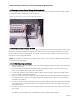
1.1 Connecting the CMA Cables to the System ....................................................................................... 2
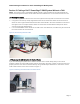
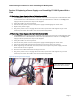
1.2 Routing the Power Cables Through the Strain Reliefs ...................................................................... 3
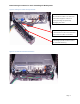
1.3 Routing the Cables Through the CMA ................................................................................................. 3
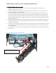
1.4 Left-Side Mounting Instructions ........................................................................................................... 3
1.5 Right-Side Mounting Instructions ......................................................................................................... 5
Section 2: Cabling a Dell™ PowerEdge™ R810 System Without a CMA .................................................... 6
2.1 Routing the Cables .................................................................................................................................. 6
2.2 Removing the CMA Brackets for Shallow Racks ................................................................................ 6
Section 3: Replacing a Power Supply on a PowerEdge™ R810 System With a CMA ................................ 7
3.1 Replacing a Power Supply with a Left-Side Mounted CMA .............................................................. 7
3.2 Replacing a Power Supply with a Right-Side Mounted CMA ........................................................... 7
Table of Figures
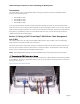
Figure 1: System with Cables Installed
.................................................................................................................. 2
Figure 2: Routing Power Cables Through the Strain Reliefs
............................................................................. 3
Figure 3: Routing the Cables Through the CMA
................................................................................................. 4
Figure 4: Left-Side Mounted CMA Installation
..................................................................................................... 4
Figure 5: Right-Side Mounted CMA Installation
.................................................................................................. 5
Figure 6: Cable Routing Without a CMA
............................................................................................................... 6
Figure 7: Removing the CMA Brackets for Shallow Racks
................................................................................. 6
Figure 8: Replacing the Power Supply
................................................................................................................... 7