Cable Routing Procedures for Dell™ PowerEdge™ R510 Systems A Dell Technical White Paper Dell │ Datacenter Infrastructure Engineering By Riyad Moe and Jose L.
Cable Routing Procedures for Dell™ PowerEdge™ R510 Systems THIS WHITE PAPER IS FOR INFORMATIONAL PURPOSES ONLY, AND MAY CONTAIN TYPOGRAPHICAL ERRORS AND TECHNICAL INACCURACIES. THE CONTENT IS PROVIDED AS IS, WITHOUT EXPRESS OR IMPLIED WARRANTIES OF ANY KIND. © 2009 Dell Inc. All rights reserved. Reproduction of this material in any manner whatsoever without the express written permission of Dell Inc. is strictly forbidden. For more information, contact Dell.
Cable Routing Procedures for Dell™ PowerEdge™ R510 Systems Contents Introduction ...............................................................................................................................................................2 Section 1: Cabling a Dell™ PowerEdge™ R510 With a Cable Management Arm (CMA) ............................................2 1.1 Connecting the CMA Cables to the System ..................................................................................................
Cable Routing Procedures for Dell™ PowerEdge™ R510 Systems Introduction This white paper covers recommended cable routing procedures for Dell™ PowerEdge™ R510 systems in the following racks: • • • • PowerEdge™ 4210 PowerEdge™ 2410 PowerEdge™ 4220 PowerEdge™ 2420 If you are using the optional CMA, following these procedures will allow you to extend the system from the rack for service without powering down or disconnecting the cables.
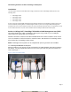
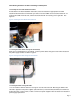
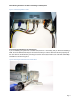
Cable Routing Procedures for Dell™ PowerEdge™ R510 Systems 1.2 Installing the Inner CMA Attachment Bracket As described in the Rack Installation Instructions, locate and attach the appropriate inner CMA attachment bracket based on which side you wish to mount the CMA. Use the bracket marked “A” for mounting the CMA on the left side, and the bracket marked “B” for mounting on the right side. See Figure 2. Figure 2: Attaching the Inner CMA Attachment Bracket 1.
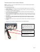
Cable Routing Procedures for Dell™ PowerEdge™ R510 Systems NOTE: For guidelines on how to route cables within the rack, refer to the Dell Best Practices Guide for Rack Enclosures white paper. 1.5 Left-Side Mounting Instructions 1. Install the CMA on the rear left side of the rails by attaching both CMA housings to the attachment brackets on the rails. 2. Route the cables through the CMA while avoiding twisting the cables. Use the hook and loop straps on the CMA to secure the cables. See Figure 4. 3.
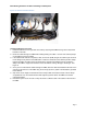
Cable Routing Procedures for Dell™ PowerEdge™ R510 Systems Figure 5: Left-Side Mounted CMA Installation 1.6 Right-Side Mounting Instructions 1. Install the CMA on the rear right side of the rails by attaching both CMA housings to the attachment brackets on the rails. 2. Route the cables through the CMA while avoiding twisting the cables. Use the hook and loop straps on the CMA to secure the cables. 3.
Cable Routing Procedures for Dell™ PowerEdge™ R510 Systems Figure 6: Right-Side Mounted CMA Installation KVM dongle placed outside the basket for Right-Side Mounting. Section 2: Cabling a Dell™ PowerEdge™ R510 System Without a CMA NOTE: The CMA on Dell™ PowerEdge™ R510 systems is optional. Without the CMA installed, the system must be powered down and all cables disconnected before it can be removed from the rack. 2.1 Routing the Cables 1.
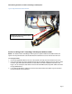
Cable Routing Procedures for Dell™ PowerEdge™ R510 Systems Figure 7: Cable Routing Without a CMA 2.2 Removing the CMA Brackets for Shallow Racks If you are installing the system into a shallow rack (less than 1 meter deep) and you will not be installing a CMA, the outer CMA brackets may be removed if necessary in order to allow the rails to fit properly into the rack. Remove the brackets by removing the screws used to attach them to the rails with a #2 Phillips screwdriver as shown in Figure 8.
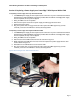
Cable Routing Procedures for Dell™ PowerEdge™ R510 Systems Section 3: Replacing a Power Supply on a PowerEdge™ R510 System With a CMA 3.1 Replacing a Power Supply with a Left-Side Mounted CMA 1. If the bottom power supply must be replaced, then remove the tray from underneath the CMA as described in the CMA Installation Instructions provided with the CMA kit. If the top power supply must be replaced, this step can be skipped. 2. Swing the CMA to its service position. 3.
Cable Routing Procedures for Dell™ PowerEdge™ R510 Systems Figure 10: Replacing the Power Supply Section 4: Cabling a PowerEdge™ R510 System Installed in Static Rails NOTE: The CMA is compatible with the sliding rails only, not the static rails. 1. Follow the instructions contained in the Rack Installation Instructions found in the static rail kit to install the server into a two-post or four-post rack. 2.