Cable Routing Procedures for Dell PowerEdge T620 Systems Cable Routing Procedures for Dell™ PowerEdge™ T620 Systems This Dell Technical White Paper explains the best practices for routing and securing the cables exiting the back of the T620 systems. Greg Henderson and Jose L.
Cable Routing Procedures for Dell PowerEdge T620 Systems This document is for informational purposes only and may contain typographical errors and technical inaccuracies. The content is provided as is, without express or implied warranties of any kind. © 2012 Dell Inc. All rights reserved. Dell and its affiliates cannot be responsible for errors or omissions in typography or photography. Dell, the Dell logo, and PowerEdge are trademarks of Dell Inc.
Cable Routing Procedures for Dell PowerEdge T620 Systems Contents Introduction ............................................................................................................. 4 Section 1: Cabling a PowerEdge T620 with a CMA ................................................................ 4 1.1. Connecting the cables to the system ................................................................... 4 1.2. Routing the power cables through the strain reliefs ...................................
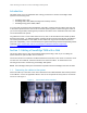
Cable Routing Procedures for Dell PowerEdge T620 Systems Introduction This white paper covers recommended cable routing procedures for the Dell™ PowerEdge™ T620 systems in the following racks: PowerEdge 2410, 4210 PowerEdge 2420, 4220, 4820 (including wide and deep versions) PowerEdge Energy Smart 4020S, 4620S If you are using the optional cable management arm (CMA), following these procedures will allow you to extend the system from the rack for service without powering down or disconnecting the c
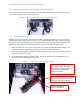
Cable Routing Procedures for Dell PowerEdge T620 Systems 1.2. Routing the power cables through the strain reliefs After you have installed the tray and cables, route the power cables through the strain reliefs located on the power supply handles as shown in Figure 2. Figure 2. Routing power cables through the strain reliefs 1.3. Installing the CMA NOTE: If you are installing fiber-optic cables in the CMA, a cable bend radius of at least 1 inch must be maintained throughout the length of the cable.
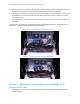
Cable Routing Procedures for Dell PowerEdge T620 Systems 4. Once you have routed all of the cables through the CMA, dress the cable slack between the back of the system and the entrance of the CMA using the tie wraps provided in the CMA kit. 5. Clip off the excess length of material from the tie wraps. Make sure that the heads of the tie wraps are positioned so as to avoid interference with adjacent systems. Return the CMA to the closed (retracted) position. 6.
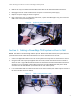
Cable Routing Procedures for Dell PowerEdge T620 Systems 2. Remove the tray from underneath the CMA as described in the CMA Installation Instructions. 3. Disengage the strain relief and disconnect the power cord from the power supply. 4. Replace the power supply as shown in Figure 6. 5. Plug in the power cord, re-engage the strain relief, replace the CMA support tray, and return the CMA to the closed (retracted) position. Figure 6.