Dell PowerEdge T420 Systems Owner's Manual Regulatory Model: E20S Series Regulatory Type: E20S001
Notes, Cautions, and Warnings NOTE: A NOTE indicates important information that helps you make better use of your computer. CAUTION: A CAUTION indicates either potential damage to hardware or loss of data and tells you how to avoid the problem. WARNING: A WARNING indicates a potential for property damage, personal injury, or death. © 2013 Dell Inc. All Rights Reserved.
Contents 1 About Your System......................................................................................................................8 Front-Panel Features And Indicators—Tower Mode...............................................................................................8 Front-Panel Features And Indicators—Rack Mode............................................................................................... 12 LCD Panel Features...........................................................
Boot Manager Screen......................................................................................................................................35 UEFI Boot Menu............................................................................................................................................... 35 Embedded System Management............................................................................................................................35 iDRAC Settings Utility....................
Hard-Drive Backplane............................................................................................................................................ 59 Removing The Hard-Drive Backplane ............................................................................................................. 59 Installing The Hard-Drive Backplane............................................................................................................... 65 Four-Slot Hard-Drive Blank.........................
Installing A Redundant AC Power Supply........................................................................................................ 95 Removing The Power Supply Blank................................................................................................................. 96 Installing The Power Supply Blank.................................................................................................................. 96 Replacing The Power Supply Divider.................................
Troubleshooting A Damaged System................................................................................................................... 122 Troubleshooting The System Battery................................................................................................................... 122 Troubleshooting A Non-Redundant Power Supply...............................................................................................123 Troubleshooting Redundant Power Supplies.......................
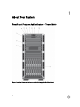
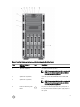
About Your System Front-Panel Features And Indicators—Tower Mode Figure 1. Front-Panel Features and Indicators—2.
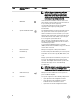
Figure 2. Front-Panel Features and Indicators—3.5 Inch Hot-Swappable Hard-Drive Chassis Item Indicator, Button, or Connector 1 Tape drive (optional) Icon Description One optional 5.25 inch tape drive. NOTE: If your system is installed with a double-width GPU card, the system supports only one 5.25 inch removable media storage device. 2 Optical drive 2 (optional) 3 Optical drive 1 (optional) Up to two optional SATA DVD-ROM drive or DVD+/-RW drive.
Item Indicator, Button, or Connector Icon Description NOTE: On Advanced Configuration and Power Interface (ACPI)-compliant operating systems, turning off the system using the power button causes the system to perform a graceful shutdown before power to the system is turned off. 5 NMI button Used to troubleshoot software and device driver errors when running certain operating systems. This button can be pressed using the end of a paper clip.
Figure 3. Front-Panel Features and Indicators—3.5 Inch Cabled Hard-Drive Chassis NOTE: Cabled hard-drive systems are not rackable. Item Indicator, Button, or Connector Icon Description 1 Tape drive (optional) One optional 5.25 inch tape drive. 2 Optical drive (optional) One optional SATA DVD-ROM drive or DVD+/-RW drive. 3 Power-on indicator, power button The power-on indicator lights when the system power is on. The power button controls the power supply output to the system.
Item Indicator, Button, or Connector Icon Description Use this button only if directed to do so by qualified support personnel or by the operating system documentation. 5 System identification button The identification buttons on the front and back panels of the system can be used to locate a particular system within a rack. When one of these buttons is pressed, the LCD panel on the front chassis and the system status indicator on the back chassis flash until one of the buttons is pressed again.
Item Indicator, Button, or Connector Icon Description NOTE: On ACPI-compliant operating systems, turning off the system using the power button causes the system to perform a graceful shutdown before power to the system is turned off. 2 NMI button Used to troubleshoot software and device driver errors when running certain operating systems. This button can be pressed using the end of a paper clip.
Item Indicator, Button, or Connector Icon Description NOTE: If your system is installed with a double-width GPU card, the system supports only one 5.25 inch removable media storage device. 12 Your system supports one of the following configurations: Hard drives • • • Up to eight 3.5 inch hot-swappable hard drives. Up to eight 2.5 inch hot-swappable hard drives installed in 3.5 inch hard-drive carriers. Up to sixteen 2.5 inch hot-swappable hard drives.
turns off after five minutes of inactivity if there are no error messages. Press one of the three navigation buttons (Select, Left, or Right) to view the Home screen. To navigate to the Home screen from another menu, continue to select the up arrow displayed, and then select the Home icon. until the Home icon is From the Home screen, press the Select button to enter the main menu.
Health Indicator Condition Corrective Action If the system is on, and in good health, the indicator lights solid blue. None required. The indicator blinks amber if the system is on or in standby, and any error exists (for example, a failed fan or hard drive) See the System Event Log or system messages for the specific issue. Invalid memory configurations can cause the system to halt at startup without any video output. See Getting Help.
Memory Indicator Condition Corrective Action The indicator blinks amber if a memory error occurs. See the system event log or system messages for the location of the failed memory. Reinstall the memory device. If the problem persists, see Getting Help. PCIe Indicator Condition Corrective Action The indicator blinks amber if a PCIe card experiences an error. Restart the system. Update any required drivers for the PCIe card. Re-install the card. If the problem persists, see Getting Help.
Drive-Status Condition Indicator Pattern (RAID Only) Blinks amber four times per second Drive failed Blinks green slowly Drive rebuilding Steady green Drive online Blinks green three Rebuild aborted seconds, amber three seconds, and off six seconds Back-Panel Features And Indicators Figure 7.
Item Indicator, Button, or Connector 1 Power supplies (PSU1 and PSU2) Icon Description Redundant power supply Up to two 495 W, 750 W, or 1100 W redundant AC power supplies. Non-redundant power supply One 550 W non-redundant AC power supply. NOTE: Non-redundant power supply is supported in systems with cabled hard drives and systems with an x8 backplane. 2 PCIe expansion card slots (6) Allows you to connect up to six full-height PCI expansion cards.
NIC Indicator Codes Figure 8. NIC Indicator 1. link indicator 2. activity indicator Indicator Indicator Code Link and activity indicators are off The NIC is not connected to the network. Link indicator is green The NIC is connected to a valid network at its maximum port speed (1 Gbps or 10 Gbps). Link indicator is amber The NIC is connected to a valid network at less than its maximum port speed. Activity indicator is blinking green Network data is being sent or received.
Power Indicator Pattern Condition Flashing amber Indicates a problem with the power supply. CAUTION: When correcting a power supply mismatch, replace only the power supply with the flashing indicator. Swapping the opposite power supply to make a matched pair can result in an error condition and unexpected system shutdown. To change from a High Output configuration to a Low Output configuration or vice versa, you must power down the system.
Other Information You May Need WARNING: See the safety and regulatory information that shipped with your system. Warranty information may be included within this document or as a separate document. • The Getting Started Guide provides an overview of setting up your system, and technical specifications. This document is available online at www.dell.com/support/manuals. • The rack documentation included with your rack solution describes how to install your system into a rack, if required.
Using The System Setup And Boot Manager 2 System Setup enables you to manage your system hardware and specify BIOS-level options. The following keystrokes provide access to system features during startup: Keystroke Description Enters the System Setup. Enters System Services, which opens the Dell Lifecycle Controller 2 (LC2).
You must select the boot mode in the Boot Mode field of the Boot Settings screen of System Setup. Once you specify the boot mode, the system boots in the specified boot mode and you then proceed to install your operating system from that mode. Thereafter, you must boot the system in the same boot mode (BIOS or UEFI) to access the installed operating system. Trying to boot the operating system from the other boot mode will cause the system to halt at startup.
Menu Item Description System BIOS This option is used to view and configure BIOS settings. iDRAC Settings This option is used to view and configure iDRAC settings. Device Settings This option is used to view and configure device settings. System BIOS Screen NOTE: The options for System Setup change based on the system configuration. NOTE: System Setup defaults are listed under their respective options in the following sections, where applicable.
Memory Settings Screen Menu Item Description System Memory Size Displays the amount of memory installed in the system. System Memory Type Displays the type of memory installed in the system. System Memory Speed Displays the system memory speed. System Memory Voltage Displays the system memory voltage. Video Memory Displays the amount of video memory. System Memory Testing Specifies whether system memory tests are run during system boot. Options are Enabled and Disabled.
Menu Item Description Adjacent Cache Line Prefetch Allows you to optimize the system for applications that require high utilization of sequential memory access. By default, the Adjacent Cache Line Prefetch option is set to Enabled. You can disable this option for applications that require high utilization of random memory access. Hardware Prefetcher Allows you to enable or disable hardware prefetcher. By default, the Hardware Prefetcher option is set to Enabled.
Menu Item Description Port C Auto enables BIOS support for the device attached to SATA port C. Off disables BIOS support for the device. By default, Port C is set to Auto. Port D Auto enables BIOS support for the device attached to SATA port D. Off disables BIOS support for the device. By default, Port D is set to Auto. Port E Auto enables BIOS support for the device attached to SATA port E. Off disables BIOS support for the device. By default, Port E is set to Auto.
Menu Item Description NOTE: This option is displayed only if IDSDM is installed on the system board. Internal SD Card Redundancy If set to Mirror mode, data is written on both SD cards. If any one of the SD card fails, data is written to the active SD card. Data from this card is copied to the replacement SD card at the next boot. By default, Internal SD Card Redundancy option is set to Mirror. NOTE: This option is displayed only if IDSDM is installed on the system board.
Menu Item Description Remote Terminal Type Allows you to set the remote console terminal type. By default, the Remote Terminal Type option is set to VT 100/VT 220. Redirection After Boot Allows you to enable or disable to the BIOS console redirection when the operating system is loaded. By default, the Redirection After Boot option is set to Enabled. System Profile Settings Screen Menu Item Description System Profile Allows you to set the system profile.
System Security Screen Menu Item Description Intel AES-NI The Intel AES-NI option improves the speed of applications by performing encryption and decryption using the Advanced Encryption Standard Instruction Set and is set to Enabled by default. System Password Allows you to set the system password. This option is set to Enabled by default and is read-only if the password jumper is not installed in the system. Setup Password Allows you to set the setup password.
Menu Item Description Keyboard NumLock Allows you to set whether the system boots with the NumLock enabled or disabled. By default the Keyboard NumLock is set to On. NOTE: This field does not apply to 84-key keyboards. Report Keyboard Errors Allows you to set whether keyboard-related error messages are reported during system boot. By default, the Report Keyboard Errors field is set to Report. F1/F2 Prompt on Error Allows you to enable or disable the F1/F2 prompt on error.
A message prompts you to re-enter the system password. 6. Re-enter the system password that you entered earlier and click OK. 7. Select Setup Password, enter your system password and press or . A message prompts you to re-enter the setup password. 8. Re-enter the setup password that you entered earlier and click OK. 9. Press to return to the System BIOS screen. Press again, and a message prompts you to save the changes.
If you do not enter the correct password in three attempts, the system displays the message Invalid Password! Number of unsuccessful password attempts: System Halted! Must power down. Even after you shut down and restart the system, the error message is displayed until the correct password is entered. The following options are exceptions: • If System Password is not Enabled and is not locked through the Password Status option, you can assign a system password.
Boot Manager Screen Menu Item Description Continue Normal Boot The system attempts to boot to devices starting with the first item in the boot order. If the boot attempt fails, the system continues with the next item in the boot order until the boot is successful or no more boot options are found. BIOS Boot Menu Displays the list of available BIOS boot options (marked with asterisks). Select the boot option you wish to use and press .
Entering The iDRAC Settings Utility 1. Turn on or restart the managed system. 2. Press during Power-on Self-test (POST). 3. In the System Setup Main Menu page, click iDRAC Settings. The iDRAC Settings screen is displayed. Changing The Thermal Settings The iDRAC Settings utility enables you to select and customize the thermal control settings for your system. 1. Enter the iDRAC Settings utility. 2.
Installing System Components 3 Recommended Tools You may need the following items to perform the procedures in this section: • Key to the system keylock • #1 and #2 Phillips screwdrivers • Wrist grounding strap connected to ground Front Bezel (Optional) Installing The Front Bezel 1. Insert the bezel tabs into the bezel tab slots in the chassis. 2. Press the top end of the bezel into the chassis until the bezel locks into place. 3. Insert the bezel key in the keylock. 4.
Figure 11. Removing and Installing the Front Bezel 1. system 2. front bezel 3. keylock 4. release latch Removing The Front Bezel 1. Insert the bezel key in the keylock. 2. Keeping the keylock pressed with the bezel key, rotate the keylock to the unlocked position. 3. Press down on the release latch at the top of the bezel. 4. Rotate the top end of the bezel away from the system. 5. Unhook the bezel tabs from the slots on the front of the chassis.
Figure 12. Removing and Installing the System Feet 1. base of the tower 3. screws (4) 2. system feet (4) Installing The System Feet 1. Lay the system on its side on a flat, stable surface. 2. Secure the system feet to the base of the tower using the screws. 3. Place the system upright on a flat, stable surface and turn the system feet outward. Wheel Assembly (Optional)—Tower Mode The wheel assembly provides mobility to the system in the tower mode.
6. Offset the back wheel assembly unit slightly to the front of the system to release the retention hooks, and pull out the back wheel assembly unit. 7. If you are not replacing the wheel assembly, install the system feet. 8. Place the system on a sturdy, stable surface and if applicable, rotate the system feet outward. Figure 13. Removing and Installing the Wheel Assembly 1. support unit 2. screws for support unit (2) 3. slots on base of the tower (4) 4. wheel assembly unit (2) 5.
Opening And Closing The System WARNING: Whenever you need to lift the system, get others to assist you. To avoid injury, do not attempt to lift the system by yourself. WARNING: Opening or removing the system cover when the system is on may expose you to a risk of electric shock. CAUTION: Many repairs may only be done by a certified service technician.
Figure 14. Opening and Closing the System 1. cover release latch 2. latch release lock 3. system cover 4. system feet (4) Closing The System 1. Ensure that all internal cables are connected and placed out of the way and that no tools or extra parts are left inside the system. 2. Place the bottom edge of the system cover into the corresponding slots of the system chassis. 3. Lower the system cover onto the chassis. 4.
Figure 15. Inside the System—With Hot-Swappable Hard Drives 1. power interposer board 2. PCIe card holder (optional) 3. cooling shroud 4. internal cooling fan 5. external cooling fan (optional) 6. system feet (4) 7. heat sink for processor 2 8. expansion card slots (6) 9. heat sink for processor 1 10.
Figure 16. Inside the System—With Cabled Hard Drives 1. cabled power supply 2. PCIe card holder (optional) 3. cooling shroud 4. internal cooling fan 5. system feet (4) 6. heat sink for processor 2 7. expansion card slots (6) 8. heat sink for processor 1 9. internal hard-drive bay Optical Drives And Tape Drives (Optional) Your system supports one of the following configurations: • Systems with cabled hard drives support one optical drive and one tape drive.
Removing The Optical Drive Or Tape Drive CAUTION: Many repairs may only be done by a certified service technician. You should only perform troubleshooting and simple repairs as authorized in your product documentation, or as directed by the online or telephone service and support team. Damage due to servicing that is not authorized by Dell is not covered by your warranty. Read and follow the safety instructions that came with the product. 1. If installed, remove the front bezel. 2.
Figure 17. Removing and Installing the Optical Drive or Tape Drive 46 1. optical drive 3. release latch 2.
Figure 18. Cabling—Optical Drive and Tape Drive 1. connector for power cable extension 2. mini-SAS connector on PERC card 3. ODD2/TBU connector on system board 4. ODD1/TBU connector on system board 5. power connector on x8 backplane 6. SAS tape drive data/power connector 7. optical drive 2 power connector 8. optical drive 2 data connector 9. optical drive 1 power connector 10.
If you are installing a SAS tape drive, you must have an internal SAS expansion card installed. See Installing An Expansion Card. 2. If installed, remove the front bezel. 3. Turn off the system, including any attached peripherals, and disconnect the system from the electrical outlet and peripherals. 4. If applicable, rotate the system feet inward and lay the system on it side on a flat and stable surface.
Figure 19. Removing and Installing the Cooling Shroud 1. cooling shroud 2. chassis intrusion-switch 3. slots (2) 4. tabs on the system cooling fan (2) 5. chassis intrusion-switch connector on the system board Installing The Cooling Shroud CAUTION: Many repairs may only be done by a certified service technician. You should only perform troubleshooting and simple repairs as authorized in your product documentation, or as directed by the online or telephone service and support team.
Hard Drives—Hot-Swappable Your system supports one of the following configurations: • Up to eight 3.5 inch (SAS, SATA, or SSD) hot-swappable hard drives • Up to eight 2.5 inch (SAS, SATA, or SSD) hot-swappable hard drives installed in 3.5 inch hard-drive adapters, which are then installed in the 3.5 inch hard-drive carriers • Up to sixteen 2.
Figure 20. Removing and Installing a Hot-Swap Hard Drive 1. release button 3. hard-drive carrier handle 2. hard drive Installing A Hot-Swap Hard Drive CAUTION: Many repairs may only be done by a certified service technician. You should only perform troubleshooting and simple repairs as authorized in your product documentation, or as directed by the online or telephone service and support team. Damage due to servicing that is not authorized by Dell is not covered by your warranty.
Figure 21. Removing and Installing a 2.5 Inch Hard-Drive Blank 1. hard-drive blank 2. release button Installing A 2.5 Inch Hard-Drive Blank 1. If installed, remove the front bezel. 2. Insert the hard-drive blank into the hard-drive slot until the release button clicks into place. 3. If applicable, install the front bezel. Removing A 3.5 Inch Hard-Drive Blank CAUTION: To maintain proper system cooling, all empty hard-drive slots must have drive blanks installed. 1.
3. If applicable, install the front bezel. Removing A 2.5 Inch Hard Drive From A 3.5 Inch Hard-Drive Adapter NOTE: A 2.5 inch hard drive is installed into a 3.5 inch hard-drive adapter, which is then installed in the 3.5 inch hard-drive carrier. 1. Remove the two screws from the side of the 3.5 inch hard-drive adapter. 2. Remove the hard-drive away from the hard-drive adapter. Figure 23. Removing and Installing a 2.5 Inch Hard Drive Into a 3.5 Inch Hard-Drive Adapter 1. screws (2) 3. 2.
Figure 24. Removing and Installing a Hot-Swap Hard Drive Into a Hard-Drive Carrier 1. hard-drive carrier 2. screws (4) 3. hard drive 4.
Figure 25. Removing and Installing a Hard-Drive Adapter Into a 3.5 Inch Hard-Drive Carrier 1. hard-drive carrier 2. screws (5) 3. hard-drive adapter 4. 2.5 inch hard drive Installing A Hard Drive Or A Hard-Drive Adapter Into A Hard-Drive Carrier CAUTION: Many repairs may only be done by a certified service technician. You should only perform troubleshooting and simple repairs as authorized in your product documentation, or as directed by the online or telephone service and support team.
Removing The Internal Hard-Drive Bay CAUTION: Many repairs may only be done by a certified service technician. You should only perform troubleshooting and simple repairs as authorized in your product documentation, or as directed by the online or telephone service and support team. Damage due to servicing that is not authorized by Dell is not covered by your warranty. Read and follow the safety instructions that came with the product. 1.
Installing The Internal Hard-Drive Bay CAUTION: Many repairs may only be done by a certified service technician. You should only perform troubleshooting and simple repairs as authorized in your product documentation, or as directed by the online or telephone service and support team. Damage due to servicing that is not authorized by Dell is not covered by your warranty. Read and follow the safety instructions that came with the product. 1.
Figure 27. Removing and Installing a Cabled Hard Drive 1. hard drive connector 2. hard drive 3. internal hard-drive bay 4. screws (4) Installing A Cabled Hard Drive CAUTION: Many repairs may only be done by a certified service technician. You should only perform troubleshooting and simple repairs as authorized in your product documentation, or as directed by the online or telephone service and support team. Damage due to servicing that is not authorized by Dell is not covered by your warranty.
13. Enter the System Setup and ensure that the hard drive's controller is enabled. 14. Exit the System Setup program and reboot the system. 15. Install any software required for the hard drive operation as described in the documentation for the hard drive. Hard-Drive Backplane Your system supports one of the following configurations: • x8 SAS/SATA backplane for 3.5 inch hard drives NOTE: The x8 backplane also supports up to eight 2.5 inch (SAS, SATA, or SSD) hot-swappable hard drives installed in 3.
Figure 28. Removing and Installing an x8 Hard-Drive Backplane 60 1. x8 hard-drive backplane 3. hooks (11) 2.
Figure 29. Connectors on an x8 Hard-Drive Backplane 1. SAS B connector 2. power connector for the optical and tape drives 3. backplane power connector 4. SAS A connector 5.
Figure 30. Cabling—x8 Hard-Drive Backplane 62 1. power connector 2. SAS A connector on system board 3. I2C connector on system board 4. I2C connector on backplane 5. SAS A connector on backplane 6.
Figure 31. Removing and Installing an x16 Hard-Drive Backplane 1. x16 hard-drive backplane 3. hooks (7) 2.
Figure 32. Connectors on an x16 Hard-Drive Backplane 64 1. backplane power connector 2. backplane 3. power connector for the optical and tape drives 4. I2C connector 5. primary SAS connectors (A and B) 6.
Figure 33. Cabling—x16 Hard-Drive Backplane With Expansion Card 1. power connector on power distribution board 2. SAS B connector on PowerEdge RAID Controller (PERC) card 3. SAS A connector on PERC card 4. I2C connector on system board 5. SAS A connector on backplane 6. SAS B connector on backplane 7. backplane power connector 8. I2C connector on backplane Installing The Hard-Drive Backplane CAUTION: Many repairs may only be done by a certified service technician.
Four-Slot Hard-Drive Blank Systems with x8 hard-drive backplanes configured for software RAID support only four hard drives. The remaining harddrive slots are pre-installed with the four-slot hard-drive blank, and are not available for software RAID. Removing A Four-Slot Hard-Drive Blank CAUTION: To maintain proper system cooling, all empty hard-drive slots must have hard-drive blanks installed. NOTE: This is a service only procedure. 1. If installed, remove the front bezel. 2.
Figure 34. Installing and Removing the Four-Slot Hard-Drive Blank 1. four-slot hard-drive blank 3. screwdriver 2. release tab Installing A Four-Slot Hard-Drive Blank 1. Locate the hard drive slots numbered from four to seven. 2. Insert the four-slot hard-drive blank into the hard-drive slot, and push it until the release tabs click into place. 3. Close the system. 4. If applicable, place the system upright on a flat, stable surface and rotate the system feet outward. 5.
DIMM Type DIMMs Populated/ Channel Operating Frequency (in MT/s) Maximum DIMM Rank/ Channel 1.5 V 1.
channel 3: memory sockets B3 and B6 General Memory Module Installation Guidelines This system supports Flexible Memory Configuration, enabling the system to be configured and run in any valid chipset architectural configuration. The following are the recommended guidelines for best performance: • UDIMMs and RDIMMs must not be mixed. • x4 and x8 DRAM based DIMMs can be mixed. For more information, see Mode-Specific Guidelines. • A maximum of two UDIMMs can be populated in a channel.
Memory Optimized (Independent Channel) Mode This mode supports SDDC only for memory modules that use x4 device width and does not impose any specific slot population requirements. Memory Sparing NOTE: To use memory sparing, this feature must be enabled in the System Setup. In this mode, one rank per channel is reserved as a spare. If persistent correctable errors are detected on a rank, the data from this rank is copied to the spare rank and the failed rank is disabled.
System Capacity (in GB) DIMM Size (in GB) Number of DIMMs Organization and Speed DIMM Slot Population 24 8 3 2R x4, 1333 MT/s 2R x4, 1600 MT/s A1, A2, A3 32 8 4 2R x4, 1333 MT/s 2R x4, 1600 MT/s A1, A2, A3, A4 48 16 3 2R x4, 1333 MT/s 2R x4, 1600 MT/s A1, A2, A3 96 16 6 2R x4, 1333 MT/s 2R x4, 1600 MT/s A1, A2, A3, A4, A5, A6 128 32 4 4R x4, 1066 MT/s A1, A2, A3, A4 192 32 6 4R x4, 1066 MT/s A1, A2, A3, A4, A5, A6 Table 2.
CAUTION: Many repairs may only be done by a certified service technician. You should only perform troubleshooting and simple repairs as authorized in your product documentation, or as directed by the online or telephone service and support team. Damage due to servicing that is not authorized by Dell is not covered by your warranty. Read and follow the safety instructions that came with the product.
7. Install the cooling shroud. 8. Close the system. 9. Reconnect the system to its electrical outlet and turn the system on, including any attached peripherals. Installing Memory Modules WARNING: The memory modules are hot to the touch for some time after the system has been powered down. Allow time for the memory modules to cool before handling them. Handle the memory modules by the card edges and avoid touching the components or metallic contacts on the memory module.
3. memory-module socket alignment key 4. memory-module alignment key NOTE: When the memory module is properly seated in the socket, the levers on the memory-module socket align with the levers on the other identical sockets that have memory modules installed. 8. Repeat step 4 through step 7 of this procedure to install the remaining memory modules. 9. Replace the cooling shroud. 10. Close the system. 11.
Figure 39. Removing and Installing the Internal Cooling Fan 1. arrow 2. internal cooling fan 3. internal cooling fan power cable 4. release tab Figure 40. Cabling—Internal Cooling Fan 1. FAN1 power connector on system board 2. internal cooling fan power cable 3. securing clip on system board 4. securing clip on chassis 5.
Installing The Internal Cooling Fan CAUTION: Many repairs may only be done by a certified service technician. You should only perform troubleshooting and simple repairs as authorized in your product documentation, or as directed by the online or telephone service and support team. Damage due to servicing that is not authorized by Dell is not covered by your warranty. Read and follow the safety instructions that came with the product.
Figure 41. Removing and Installing the External Cooling Fan 1. back of the system chassis 2. lower hooks (2) 3. external cooling fan 4. screws (4) 5. upper hook 6. external cooling fan power cable slot 7. external cooling fan power cable Figure 42. Cabling—External Cooling Fan 1. external cooling fan power cable 2. securing clip on system board 3. FAN2 power connector on system board 4. securing clip on chassis 5.
Installing The External Cooling Fan CAUTION: Many repairs may only be done by a certified service technician. You should only perform troubleshooting and simple repairs as authorized in your product documentation, or as directed by the online or telephone service and support team. Damage due to servicing that is not authorized by Dell is not covered by your warranty. Read and follow the safety instructions that came with the product.
4. Locate the USB connector (INT USB) or the USB key on the system board. 5. If applicable, remove the USB key. 6. Insert the new USB key into the USB connector. 7. Close the system. 8. If applicable, place the system upright on a flat, stable surface and rotate the system feet outward. 9. Reconnect the system to its electrical outlet and turn the system on, including any attached peripherals. 10. Enter the System Setup and verify that the USB key is detected by the system. Figure 43.
5. Lift the PCIe card holder out of the chassis. 6. Close the system. 7. If applicable, place the system upright on a flat, stable surface and rotate the system feet outward. 8. If applicable, reconnect the system to its electrical outlet and turn the system on, including any attached peripherals. Figure 44. Removing and Installing the PCIe Card Holder 1. slots (2) 3. PCIe card holder 2.
Expansion Cards Expansion Card Installation Guidelines Table 3.
• Your system supports only Q4000 single-width GPU cards and Q6000 double-width GPU card. • The two-processor configuration supports one double-width or two single-width cards on slots 3 and 5. • For systems with a single GPU card, connect the GPU card power cable to the GPU power connector CN11 on the power distribution board.
Figure 45. Removing and Installing the Expansion Card 1. 2. 3. expansion card latch expansion card connector expansion card Installing An Expansion Card CAUTION: Many repairs may only be done by a certified service technician. You should only perform troubleshooting and simple repairs as authorized in your product documentation, or as directed by the online or telephone service and support team. Damage due to servicing that is not authorized by Dell is not covered by your warranty.
12. If applicable, connect the P3 power cable to the system board. 13. If applicable, install the PCIe card holder. 14. Close the system. 15. If applicable, place the system upright on a flat, stable surface and rotate the system feet outward. 16. Reconnect the system to its electrical outlet and turn the system on, including any attached peripherals. Removing A GPU Card CAUTION: Many repairs may only be done by a certified service technician.
Figure 46. Removing and Installing the GPU Card 1. 2. 3. 4. 5. 6. GPU card (double-width) SLI data connector 6–pin GPU card power connector 8–pin GPU card power connector x16 connector expansion-card latches (2) Installing A GPU Card CAUTION: Many repairs may only be done by a certified service technician. You should only perform troubleshooting and simple repairs as authorized in your product documentation, or as directed by the online or telephone service and support team.
10. Connect the cables to the GPU card. 11. Install the PCIe card holder. 12. Close the system. 13. If applicable, place the system upright on a flat, stable surface and rotate the system feet outward. 14. Reconnect the system to its electrical outlet and turn the system on, including any attached peripherals. iDRAC Ports Card The iDRAC ports card consists of the SD vFlash card slot and an iDRAC port. The iDRAC ports card is used for advanced management of the system.
Figure 47. Removing and Installing the iDRAC Ports Card 1. screw 3. iDRAC ports card connector 2. iDRAC ports card Installing The iDRAC Ports Card CAUTION: Many repairs may only be done by a certified service technician. You should only perform troubleshooting and simple repairs as authorized in your product documentation, or as directed by the online or telephone service and support team. Damage due to servicing that is not authorized by Dell is not covered by your warranty.
Replacing An SD vFlash Card 1. Locate the SD vFlash card slot on the system. 2. To remove the installed SD vFlash card, push inward on the card to release it, and pull the card from the card slot. Figure 48. Removing and Installing the SD vFlash Card 1. 3. SD vFlash card 2. SD vFlash card slot To install the SD vFlash card, hold the card with the label side facing up and insert the contact-pin end of the card into the SD vFlash card slot.
Figure 49. Removing and Installing the Internal Dual SD Module 1. SD card connector on system board 2. SD card slot 1 3. SD card slot 2 4. SD card Installing An Internal Dual SD Module CAUTION: Many repairs may only be done by a certified service technician. You should only perform troubleshooting and simple repairs as authorized in your product documentation, or as directed by the online or telephone service and support team.
Removing An Internal SD Card CAUTION: Many repairs may only be done by a certified service technician. You should only perform troubleshooting and simple repairs as authorized in your product documentation, or as directed by the online or telephone service and support team. Damage due to servicing that is not authorized by Dell is not covered by your warranty. Read and follow the safety instructions that came with the product. 1.
Removing A Processor CAUTION: Many repairs may only be done by a certified service technician. You should only perform troubleshooting and simple repairs as authorized in your product documentation, or as directed by the online or telephone service and support team. Damage due to servicing that is not authorized by Dell is not covered by your warranty. Read and follow the safety instructions that came with the product. 1. Before upgrading your system, download the latest system BIOS version from dell.
Figure 50. Removing and Installing the Heat Sink 1. heat sink 2. captive screws (4) 3. processor shield 4. standoffs (4) CAUTION: The processor is held in its socket under strong pressure. Be aware that the release lever can spring up suddenly if not firmly grasped. 11. Position your thumb firmly over the processor socket-release lever and release the lever from the locked position by pushing down and out from under the tab. Rotate the lever 90 degrees upwards. 12.
Figure 51. Removing and Installing a Processor 1. socket release lever 2. processor 3. processor shield 4. socket 5. guide 6. slot NOTE: After removing the processor, place it in an antistatic container for reuse, return, or temporary storage. Do not touch the bottom of the processor. Touch only the side edges of the processor. Installing A Processor CAUTION: Many repairs may only be done by a certified service technician.
Removing the blanks is similar to removing a processor. 9. Unpack the new processor. If the processor has previously been used in a system, remove any remaining thermal grease from the processor using a lint-free cloth. 10. Align the processor with the socket keys on the ZIF socket. 11. Install the processor in the socket: CAUTION: Positioning the processor incorrectly can permanently damage the system board or the processor. Be careful not to bend the pins in the socket. a.
Removing A Redundant AC Power Supply CAUTION: Many repairs may only be done by a certified service technician. You should only perform troubleshooting and simple repairs as authorized in your product documentation, or as directed by the online or telephone service and support team. Damage due to servicing that is not authorized by Dell is not covered by your warranty. Read and follow the safety instructions that came with the product.
4. Connect the power cable to the power supply and plug the cable into a power outlet. CAUTION: When connecting the power cable, secure the cable with the cable strap. NOTE: When installing, hot-swapping, or hot-adding a new power supply, allow several seconds for the system to recognize the power supply and determine its status. The power-supply status indicator or handle turns green to signify that the power supply is functioning properly.
5. Slide the power-supply divider out of the chassis. 6. Align the tabs of the new power-supply divider with the slots of the power supply unit cage . 7. Rotate the power-supply divider counter-clockwise and slide it in until the power-supply divider is seated in the slots of the power supply unit cage . 8. Secure the power supply divider to the chassis using the screw. 9. Install the redundant power supply module(s) or power supply blank as applicable. 10.
Removing A Non-Redundant AC Power Supply CAUTION: Many repairs may only be done by a certified service technician. You should only perform troubleshooting and simple repairs as authorized in your product documentation, or as directed by the online or telephone service and support team. Damage due to servicing that is not authorized by Dell is not covered by your warranty. Read and follow the safety instructions that came with the product. 1.
Figure 55. Removing and Installing a Non-Redundant AC Power Supply 1. screw 2. power supply unit cage 3. non-redundant power supply 4. standoff on the chassis 5. P1 cable connector 6. P2 cable connector 7. P3 cable connector 8. backplane connector Installing A Non-Redundant AC Power Supply CAUTION: Many repairs may only be done by a certified service technician.
5. Connect all the power cables to the system board, hard-drive backplane, hard drives, and optical drives, as applicable. 6. Close the system. 7. If applicable, place the system upright on a flat, stable surface and rotate the system feet outward. 8. Reconnect the system to its electrical outlet and turn the system on, including any attached peripherals.
Figure 56. Removing and Installing the Power Interposer Board and the Power Distribution Board 1. power distribution board 2. slots on power interposer board (4) 3. GPU power connector 4. power interposer board 5. hooks (4) 6. release latch 7. P6 cable connector 8. P1 cable connector 9. P2 cable connector 10. P3 cable connector 11. GPU power connector 12. backplane connector 13.
Installing The Power Interposer Board CAUTION: Many repairs may only be done by a certified service technician. You should only perform troubleshooting and simple repairs as authorized in your product documentation, or as directed by the online or telephone service and support team. Damage due to servicing that is not authorized by Dell is not covered by your warranty. Read and follow the safety instructions that came with the product. 1.
CAUTION: To avoid damage to the battery connector, you must firmly support the connector while installing or removing a battery. 5. To remove the battery, support the battery connector by pressing down firmly on the positive side of the connector. Figure 57. Removing and Installing the System Battery 1. 2. positive side of battery connector system battery 6. Lift the battery out of the securing tabs at the negative side of the connector. 7.
Removing The Control-Panel Assembly CAUTION: Many repairs may only be done by a certified service technician. You should only perform troubleshooting and simple repairs as authorized in your product documentation, or as directed by the online or telephone service and support team. Damage due to servicing that is not authorized by Dell is not covered by your warranty. Read and follow the safety instructions that came with the product. 1. If installed, remove the front bezel. 2.
Figure 59. Removing and Installing the Control-Panel Assembly With Diagnostic Indicators in a Tower-Mode System 1. control panel board 2. control-panel assembly connector 3. control-panel assembly cable connector 4. screw Figure 60. Removing and Installing the Control-Panel Assembly in a Rack-Mode System 1. LCD module ZIF connector 2. VGA module connector 3. VGA module cable connector 4.
7. 5. control-panel assembly cable connector 6. screw 7. control-panel board 8. VGA module 9. control panel for rack mode If you are replacing the control-panel assembly, remove the information tag by following the steps below: a. Locate the tabs on the information tag. b. Use a flat screwdriver to press the tabs on the tag one at a time. c. Pull the information tag out of the slot to remove it from the control-panel assembly.
Figure 62. Removing and Installing the Control Panel for Systems With an LCD Module 1. control panel 2. control-panel board 3. LCD module 4. control-panel assembly 5. tabs (3) Figure 63. Removing and Installing the Control Panel for Systems With Diagnostic Indicators 1. control panel 2. control-panel board 3. control-panel assembly 4.
Installing The Control Panel CAUTION: Many repairs may only be done by a certified service technician. You should only perform troubleshooting and simple repairs as authorized in your product documentation, or as directed by the online or telephone service and support team. Damage due to servicing that is not authorized by Dell is not covered by your warranty. Read and follow the safety instructions that came with the product. 1.
Figure 64. Removing and Installing the Control-Panel Board With LCD Module 1. LCD ZIF cable 2. LCD module ZIF connector 3. control-panel board 4. screws (3) 5. control-panel assembly Installing The Control-Panel Board For Systems With LCD Modules CAUTION: Many repairs may only be done by a certified service technician. You should only perform troubleshooting and simple repairs as authorized in your product documentation, or as directed by the online or telephone service and support team.
Removing The Control-Panel Board For Systems With Diagnostic Indicators CAUTION: Many repairs may only be done by a certified service technician. You should only perform troubleshooting and simple repairs as authorized in your product documentation, or as directed by the online or telephone service and support team. Damage due to servicing that is not authorized by Dell is not covered by your warranty. Read and follow the safety instructions that came with the product.
NOTE: The control-panel assembly with diagnostic indicators is supported on systems with cabled hard drives and systems with an x8 backplane. 1. Using the screw holes, align the control-panel board with the control-panel assembly. 2. Secure the control-panel board to the control-panel assembly using the three screws. 3. Install the control-panel assembly in the chassis. 4. Close the system. 5. Reconnect the system to its electrical outlet and turn the system on, including any attached peripherals.
Installing The LCD Module CAUTION: Many repairs may only be done by a certified service technician. You should only perform troubleshooting and simple repairs as authorized in your product documentation, or as directed by the online or telephone service and support team. Damage due to servicing that is not authorized by Dell is not covered by your warranty. Read and follow the safety instructions that came with the product. 1.
Figure 67. Removing and Installing the VGA Module 1. control panel 2. control-panel board 3. VGA module 4. securing tabs (2) 5. control-panel assembly Installing The VGA Module—Rack Mode CAUTION: Many repairs may only be done by a certified service technician. You should only perform troubleshooting and simple repairs as authorized in your product documentation, or as directed by the online or telephone service and support team.
CAUTION: If you are using the Trusted Program Module (TPM) with an encryption key, you may be prompted to create a recovery key during program or system setup. Be sure to create and safely store this recovery key. If you replace this system board, you must supply the recovery key when you restart your system or program before you can access the encrypted data on your hard drives. 1. Turn off the system, including any attached peripherals, and disconnect the system from the electrical outlet. 2.
Figure 68. Removing the System Board 1. screws (11) 3. system board 2. system board holders (2) Installing The System Board CAUTION: Many repairs may only be done by a certified service technician. You should only perform troubleshooting and simple repairs as authorized in your product documentation, or as directed by the online or telephone service and support team. Damage due to servicing that is not authorized by Dell is not covered by your warranty.
5. Install the following as applicable: a. b. c. d. e. f. g. h. i. 6. heat sink and processor memory modules internal dual SD module internal USB key expansion-cards iDRAC ports card PCIe card holder system cooling fan cooling shroud Reconnect all cables to the system board. 7. Close the system. 8. If applicable, place the system upright on a flat, stable surface and rotate the system feet outward. 9.
Converting The System From Tower Mode To Rack Mode 4 CAUTION: Many repairs may only be done by a certified service technician. You should only perform troubleshooting and simple repairs as authorized in your product documentation, or as directed by the online or telephone service and support team. Damage due to servicing that is not authorized by Dell is not covered by your warranty. Read and follow the safety instructions that came with the product.
5. Remove the system top cover by following the steps below: a. Using a #2 Phillips screwdriver, remove the three screws on the side of the system that secure the system top cover to the system chassis. b. Slide the top panel toward the back of the system until the panel hooks clear the chassis slots. c. Rotate the free side of the panel outward about 15 degrees and pull the panel clear of the system. Figure 69. Removing and Installing The System Top Cover 1. system top cover 2. screws (3) 6.
Figure 70. Removing and Installing the Rack Ears 1. front panel 2. rack ears (2) 3. screws for each rack ear (3) 12. Close the system. Rack Installation To install the system in a rack, see the system’s Rack Installation Guide.
Troubleshooting Your System 5 Safety First—For You And Your System CAUTION: Many repairs may only be done by a certified service technician. You should only perform troubleshooting and simple repairs as authorized in your product documentation, or as directed by the online or telephone service and support team. Damage due to servicing that is not authorized by Dell is not covered by your warranty. Read and follow the safety instructions that came with the product.
8. Restart the system and, if your keyboard is functioning, enter the System Setup. Verify that all USB ports are enabled on the Integrated Devices screen, in the System Setup options. If your keyboard is not functioning, you can also use remote access. If the system is not accessible, reset the NVRAM_CLR jumper inside your system and restore the BIOS to the default settings. 9. Reconnect and power on each USB device one at a time. 10.
• USB memory key • Cooling shroud • Expansion cards • Power supply(s) • Cooling fans • Processor(s) and heat sink(s) 4. • Memory modules Let the system dry thoroughly for at least 24 hours. 5. Reinstall the components you removed in step 3. 6. Close the system. 7. Turn on the system and attached peripherals. If the system does not start properly, see Getting Help. 8. If the system starts properly, shut down the system and reinstall all of the expansion cards that you removed. 9.
NOTE: If the system is turned off for long periods of time (for weeks or months), the NVRAM may lose its system configuration information. This situation is caused by a defective battery. 1. Re-enter the time and date in the System Setup. 2. Turn off the system and disconnect it from the electrical outlet for at least one hour. 3. Reconnect the system to the electrical outlet and turn on the system. 4. Enter the System Setup.
• A cooling fan is removed or has failed. • The expansion card installation guidelines have not been followed. Troubleshooting Cooling Fans CAUTION: Many repairs may only be done by a certified service technician. You should only perform troubleshooting and simple repairs as authorized in your product documentation, or as directed by the online or telephone service and support team. Damage due to servicing that is not authorized by Dell is not covered by your warranty.
16. If the memory problem is still indicated, repeat step 12 through step 15 for each memory module installed. If the problem persists after all memory modules have been checked, see Getting Help. Troubleshooting An Internal USB Key CAUTION: Many repairs may only be done by a certified service technician. You should only perform troubleshooting and simple repairs as authorized in your product documentation, or as directed by the online or telephone service and support team.
Troubleshooting An Optical Or Tape Drive CAUTION: Many repairs may only be done by a certified service technician. You should only perform troubleshooting and simple repairs as authorized in your product documentation, or as directed by the online or telephone service and support team. Damage due to servicing that is not authorized by Dell is not covered by your warranty. Read and follow the safety instructions that came with the product. 1. Try using a different CD or DVD. 2.
NOTE: When troubleshooting an expansion card, see the documentation for your operating system and the expansion card. 1. Run the appropriate diagnostic test. For more information, see Using System Diagnostics. 2. Turn off the system and attached peripherals, and disconnect the system from the electrical outlet. 3. Open the system. 4. Ensure that each expansion card is firmly seated in its connector. 5. Close the system. 6.
Using System Diagnostics 6 If you experience a problem with your system, run the system diagnostics before contacting Dell for technical assistance. The purpose of running system diagnostics is to test your system hardware without requiring additional equipment or risking data loss. If you are unable to fix the problem yourself, service and support personnel can use the diagnostics results to help you solve the problem.
System Diagnostic Controls Menu Description Configuration Displays the configuration and status information of all detected devices. Results Displays the results of all tests that are executed. System Health Provides the current overview of the system performance. Event Log Displays a time-stamped log of the results of all tests run on the system. This is displayed if at least one event description is recorded.
Jumpers And Connectors 7 System Board Jumper Settings For information on resetting the password jumper to disable a password, see Disabling A Forgotten Password. Table 5. System Board Jumper Settings Jumper Setting Description PWRD_EN The password feature is enabled (pins 2–4). (default) The password feature is disabled (pins 4–6). iDRAC local access is unlocked at the next AC power cycle. NVRAM_CLR (default) The configuration settings are cleared at the next system boot (pins 3–5).
System Board Jumpers And Connectors Figure 71.
Item Connector Description 14 USB4 TOP, USB5, USB6 BOT USB connectors 15 USB1 TOP, USB2, USB3 BOT USB connectors 16 NIC1 TOP, NIC2 BOT NIC connectors 17 COM TOP/VGA BOT Serial connector/video connector 18 INTRUSION Chassis intrusion switch connector 19 CPU2 Processor 2 20 I2V_2/P2 Power connector 21 12V_1/P3 Power connector 22 A6,A3,A5,A3,A4,A1 Memory module sockets 23 CPU1 Processor socket 24 FAN2 External cooling fan connector 25 BP_CONN Backplane connector 26 BATTER
NOTE: If you assign a new system and/or setup password with the jumper on pins 4 and 6, the system disables the new password(s) the next time it boots. 5. Reconnect the system to its electrical outlet and turn the system on, including any attached peripherals. 6. Turn off the system, including any attached peripherals, and disconnect the system from the electrical outlet. 7. Open the system. 8. Move the jumper on the system-board jumper from pins 4 and 6 to pins 2 and 4. 9. Close the system. 10.
Technical Specifications 8 Processor Processor type One or two Intel Xeon processors E5-2400 and E5-2400 v2 product family Expansion Bus Bus type PCI Express Generation 3 and 2 Expansion slots (Slot 1) One full-height, half-length x4 PCIe Gen2 card slot connected to Platform Controller Hub (PCH) (Slot 2) One full-height, full-length x1 PCIe Gen2 card slot connected to PCH (Slot 3) One full-height, full-length x16 PCIe Gen3 card slot connected to processor 1 (Slot 4) One full-height, full-length x4 PCI
Memory UDIMMs 48 GB Drives Hard drives Four–hard-drive systems Up to four 3.5 inch, internal, cabled SATA, nearline SAS, or SAS (15K) hard drives. Eight–hard-drive systems Up to eight 3.5 inch, internal, hot-swappable SATA, nearline SAS, SAS (15K) hard drives. NOTE: 2.5 inch hard drives in 3.5 inch carriers are supported for SAS, SAS SSD, and SATA SSD hard drives. Sixteen–hard-drive systems Optical drive Up to sixteen 2.
Connectors NOTE: One card slot is dedicated for redundancy. Video Video type Integrated Matrox G200 Video memory 16 MB shared Expanded Operating Temperature NOTE: When operating in the expanded temperature range, system performance may be impacted. NOTE: When operating in the expanded temperature range, ambient temperature warnings may be reported on the LCD and in the System Event Log. < 10% of annual operating hours 5 °C to 40 °C at 5% to 85% RH with 26 °C dew point.
Environmental Temperature (Continuous Operation) Temperature Ranges (for altitude less than 950 m or 3117 ft) 10 °C to 35 °C (50 °F to 95 °F) with no direct sunlight on the equipment. Humidity Percentage Range 10% to 80% Relative Humidity with 26 °C (78.8 °F) maximum dew point. Relative Humidity Storage 5% to 95% RH with 33 °C (91 °F) maximum dew point. Atmosphere must be non-condensing at all times. Maximum Vibration Operating 0.26 Grms at 5 Hz to 350 Hz (all operation orientations). Storage 1.
Environmental Conductive Dust NOTE: Applies to data center and non-data center environments. Corrosive Dust NOTE: Applies to data center and non-data center environments. Air must be free of conductive dust, zinc whiskers, or other conductive particles. • • Air must be free of corrosive dust. Residual dust present in the air must have a deliquescent point less than 60% relative humidity. Gaseous Contamination NOTE: Maximum corrosive contaminant levels measured at ≤50% relative humidity.
System Messages 9 LCD Messages NOTE: Applicable only if your system has an LCD display. The LCD messages consist of brief text messages that refer to events recorded in the System Event Log (SEL). For information on the SEL and configuring system management settings, see the systems management software documentation. NOTE: If your system fails to boot, press the System ID button for at least 5 seconds until an error code is displayed on the LCD. Record the code, then see System Error Messages.
Error Code AMP0302 Message Information Message The system board current is greater than the upper warning threshold. Details System board current is outside of the optimum range. Action AMP0303 ASR0001 ASR0002 ASR0003 140 Review system power policy. 2. Check system logs for power related failures. 3. Review system configuration changes. 4. If the issue persists, see Getting Help. Message The system board current is greater than the upper critical threshold.
Error Code BAT0002 BAT0017 CPU0000 CPU0001 CPU0005 CPU0010 Message Information Details The operating system or an application failed to communicate within the time-out period. The system was power-cycled. Action Check the operating system, application, hardware, and system event log for exception events. Message The system board battery has failed. LCD Message The system board battery has failed. Check battery. Details The system board battery is either missing or bad.
Error Code CPU0023 CPU0204 Message Information Action Review system logs for power or thermal exceptions. Message CPU is absent. LCD Message CPU is absent. Check CPU. Action Verify processor installation. If present, re-seat the processor. Message CPU voltage is outside of range. LCD Message CPU voltage is outside of range. Re-seat CPU.
Error Code Message Information Details Action CPU0703 FAN0001 Check system and operating system logs for exceptions. If no exceptions are found, continue. 2. Turn off the system and remove input power for one minute. 3. Ensure the processor is seated correctly. 4. Reapply input power and turn on the system. 5. If the issue persists, see Getting Help. CPU bus initialization error detected. LCD Message CPU bus initialization error detected. Power cycle system.
Error Code FAN1201 HWC1001 HWC2003 HWC2005 MEM0000 MEM0001 144 Message Information Details Fan operating speed is out of range. Action Remove and reinstall the fan. If the issue persists, see Getting Help. Message Fan redundancy is lost. LCD Message Fan redundancy is lost. Check fans. Details Fan has failed. Action Remove and reinstall failed fans or install additional fans. Message The is absent. LCD Message The is absent. Check hardware.
Error Code MEM0007 MEM0701 MEM0702 MEM1205 MEM1208 Message Information Details The memory module has encountered an uncorrectable error. System performance may be degraded. The operating system and/or applications may fail as a result. Action Re-seat the memory modules. If the issue persists, see Getting Help. Message Unsupported memory configuration; check memory device at location . LCD Message Unsupported memory configuration. Check memory .
Error Code MEM8000 PCI1302 PCI1304 PCI1308 PCI1320 PCI1342 146 Message Information Message Correctable memory error logging disabled for a memory device at location . LCD Message SBE log disabled on . Re-seat memory. Details Errors are being corrected but no longer logged. Action Review system logs for memory exceptions. Reinstall memory at location . Message A bus time-out was detected on a component at bus device function .
Error Code PCI1348 PCI1360 PDR0001 PDR1016 PST0128 PST0129 Message Information Action Cycle input power, update component drivers, if device is removable, reinstall the device. Message A PCI parity error was detected on a component at slot . LCD Message PCI parity error on slot . Re-seat PCI card. Details System performance may be degraded, or system may fail to operate. Action Cycle input power, update component drivers, if device is removable, reinstall the device.
Error Code PSU0001 PSU0002 PSU0003 PSU0006 PSU0016 Message Information Details System BIOS detected memory, but was unable to configure the memory for system operation. Action Compare system memory installation to supported system memory configurations. Message Power supply failed. LCD Message PSU failed. Check PSU. Action Remove and reinstall the power supply. If the issue persists, see Getting Help. Message A predictive failure detected on power supply .
Error Code PSU0031 PSU0032 PSU0033 PSU0034 Message Information Message Cannot communicate with power supply . LCD Message Cannot communicate with PSU . Re-seat PSU. Details The power supply may operate, however power supply monitoring is degraded. System performance may be degraded. Action Remove and reinstall the power supply. If the issue persists, see Getting Help. Message The temperature for power supply is in a warning range.
Error Code Message Information Details Action PSU0037 PSU0076 PSU1201 PSU1204 PWR1004 150 This failure may be the result of an electrical issue with cables or subsystem components in the system. 1. Remove and reinstall the power supply. 2. Check cables and subsystem components in the system for damage. 3. If the issue persists, see Getting Help. Message Fan failure detected on power supply . LCD Message Fan failure detected on PSU . Check PSU.
Error Code PWR1005 PWR1006 RFM1008 RFM1014 RFM1201 RFM2001 Message Information Action Check the event log for power supply failures. Review system configuration and power consumption and upgrade or install power supplies accordingly. Message The system performance degraded because the user-defined power capacity has changed. Details The user-defined power settings have affected system operation. Action If unintended, review system configuration changes and power policy.
Error Code RFM2002 RFM2004 RFM2006 SEC0031 SEC0033 SEL0006 SEL0008 152 Message Information Message Internal Dual SD Module is offline. Details The SD card module is installed but may be improperly installed or configured incorrectly. Action Reinstall the SD module. Message Failure detected on Internal Dual SD Module . LCD Message Internal Dual SD Module failed. Check SD Card. Details The SD card module is installed but improperly configured or failed to initialize.
Error Code SEL0012 SEL1204 TMP0118 TMP0119 TMP0120 TMP0121 Message Information Action Backup and clear log. Message Could not create or initialize the system event log. Details If the system event log fails to initialize, platform status and failure events are not captured. Some management software do not report platform exceptions. Action Reboot the management controller or iDRAC. Cycle system input power. If problem persists call support.
Error Code VLT0204 Message Information LCD Message System inlet temperature is outside of range. Check Fans. Details Ambient air temperature is too warm or one or more fans may have failed. Action Check the system operating environment and review event log for fan failures. Message The system board voltage is outside of the allowable range. LCD Message System board voltage is outside of range. Details System hardware detected an over voltage or under voltage condition.
Getting Help 10 Contacting Dell NOTE: If you do not have an active Internet connection, you can find contact information on your purchase invoice, packing slip, bill, or Dell product catalog. Dell provides several online and telephone-based support and service options. Availability varies by country and product, and some services may not be available in your area. To contact Dell for sales, technical support, or customer service issues: 1. Visit dell.com/support 2. Select your support category. 3.