Contents: Dell PowerVault 200S, 201S, 210S, and 211S Storage Systems Installation and Service Guide Dell™ PowerVault™ 200S, 201S, 210S, and 211S Storage Systems Installation and Service Guide You must right-click the link for a portable document format (PDF) file and save the file to your hard-disk drive. Attempting to link directly to large PDF files causes your system to freeze. To save PDF files (files with an extension of .
Contents: Dell PowerVault 200S, 201S, 210S, and 211S Storage Systems Installation and Service Guide Information in this document is subject to change without notice. © 2000 Dell Computer Corporation. All rights reserved. Reproduction in any manner whatsoever without the written permission of Dell Computer Corporation is strictly forbidden. Reproduction in any manner whatsoever without the written permission of Dell Computer Corporation is strictly forbidden.
!"#$ 4390398 2xxS Storage System Features . . . . . . . . . . . . . . . . . . . . . . . . . . . . . . . . . . . . . . . . 200S and 201S Storage System Features . . . . . . . . . . . . . . . . . . . . . . . . . . . . 210S and 211S Storage System Features . . . . . . . . . . . . . . . . . . . . . . . . . . . . System Requirements. . . . . .
!"#$ ! " " " ! # Configuring the ESEM or SEMM for Cluster Operation . . . . . . . . . . . . . . . . . . . . . 4-2 Installing the ESEM or SEMM . . . . . . . . . . . . . . . . . . . . . . . . . . . . . . . . . . . . . . . . 4-3 Managing the PowerVault 2xxS Storage System in a Cluster Configuration . . . . .
!"#$ Removing and Reinstalling the Lock Bar . . . . . . . . . . . . . . . . . . . . . . . . . . . . . . . . Installing Redundant Components Procedures . . . . . . . . . . . . . . . . . . . . . . . . . . . Recommended Tools . . . . . . . . . . . . . . . . . . . . . . . . . . . . . . . . . . . . . . . . . . . Installing the Redundant Power Supply. . . . . . . . . . . . . . . . . . . . . . . . . . . . . . . . .
!"#$ Power Protection Devices. . . . . . . . . . . . . . . . . . . . . . . . . . . . . . . . . . . . . . . . . . . . Surge Protectors . . . . . . . . . . . . . . . . . . . . . . . . . . . . . . . . . . . . . . . . . . . . . . . Line Conditioners . . . . . . . . . . . . . . . . . . . . . . . . . . . . . . . . . . . . . . . . . . . . . . . Uninterruptible Power Supply . . . . . . . . . . . . . . . . . . . . . . . . . . . . . . . .
- " 33 ( !"#$ " 4 Figure 1-1. Figure 1-2. Figure 3-1. Figure 3-2. Figure 3-3. Figure 3-4. Figure 3-5. Figure 4-1. Figure 4-2. Figure 5-1. Figure 5-2. Figure 5-3. Figure 5-4. Figure 6-1. Figure 6-2. Figure 6-3. Figure 6-4. Figure 6-5. Figure 6-6. Figure 7-1. Figure 7-2. Figure 7-3. Figure 7-4. Figure 7-5. Figure 7-6. Figure 7-7. Figure 7-8. Figure 7-9.
* 3 !"#$ Figure 7-15. Figure 7-16. Figure 7-17. Figure 7-18. Figure 7-19. Figure 7-20. Figure 8-1. Figure C-1. Figure C-2. Figure C-3. Figure C-4. Removing the Power-Supply Blank . . . . . . . . . . . . . . . . . . . . . . . . . 7-27 Inserting the Redundant Power Supply. . . . . . . . . . . . . . . . . . . . . . 7-28 Removing the Cooling-Fan Blank. . . . . . . . . . . . . . . . . . . . . . . . . . . 7-29 Inserting the Redundant Cooling Fan . .
!" Use the following safety guidelines to ensure your own personal safety and to help protect your computer or storage system from potential damage. Throughout this guide, blocks of text may be accompanied by an icon and printed in bold type or in italic type.
!" $ % & 1 1" ) !"# $ % & ' ( ) *+,+% -* ,. ' % *+ %/ !* .0 # . 1 & 2% ' / * + $ +% !3 0 !* "04 * + . . 0! #+' 2 $ !"# % & ' ( *.
!" — An object has fallen into the product. — The product has been exposed to water. — The product has been dropped or damaged. — The product does not operate correctly when you follow the operating instructions. Keep your system components away from radiators and heat sources. Also, do not block cooling vents. Do not spill food or liquids on your system components, and never operate the product in a wet environment.
!" Observe extension cable and power strip ratings. Make sure that the total ampere rating of all products plugged into the extension cable or power strip does not exceed 80 percent of the extension cable or power strip ampere ratings limit. Do not use appliance/voltage converters or kits sold for appliances with your Dell product.
!" Observe the following precautions for rack stability and safety. Also refer to the rack installation documentation accompanying the system and the rack for specific warning and/or caution statements and procedures. Server and storage systems are considered to be components in a rack. Thus, “component” refers to any server or storage system, as well as to various peripherals or supporting hardware.
!" Do not step on or stand on any system/component when servicing other systems/components in a rack. ! " # $% Observe the following guidelines when working with options: Do not connect or use a modem or telephone during a lightning storm. There may be a risk of electrical shock from lightning. Never connect or use a modem or telephone in a wet environment.
!" While you work, periodically touch an unpainted metal surface on the computer chassis to dissipate any static electricity that might harm internal components. 3. Disconnect your computer and devices from their power sources. Also, disconnect any telephone or telecommunication lines from the computer. Doing so reduces the potential for personal injury or shock.
!" 0 <, * = ! 1 # .
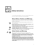
!" 1 Monitor screen at or below eye level 2 Wrists relaxed and flat 3 Arms at desk level 4 Feet flat on the floor 5 Monitor and keyboard positioned directly in front of user xi
xii !"
!" !701,.0 This guide is intended for users of the Dell PowerVault 200S, 201S, 210S, and 211S storage systems (hereafter called 2xxS storage systems) who want to learn about its features and operation and for qualified service technicians who upgrade or service the storage system.
W W !" Appendix D, "Limited Warranty and Return Policy," describes the warranty for the storage system and the "Total Satisfaction" Return Policy. "Abbreviations and Acronyms" defines the acronyms and abbreviations used in this guide.
!" $ % & $ % & ! " " # # " # ! $ The following list defines (where appropriate) and illustrates typographical conventions used as visual cues for specific elements of text throughout this document: W Interface components are window titles, button and icon names, menu names and selections, and other options that appear on
!" Example: “Type and press .” W Variables are placeholders for which you substitute a value. They are presented in italics.
,QWURGXFWLRQ The Dell™ PowerVault™ 2xxS storage systems are high-performance storage systems that offer extensive reliability and server management features. This chapter describes the features and software requirements of these storage systems. All PowerVault 2xxS storage systems offer the following features. Features for specific PowerVault 2xxS storage systems are listed after the common features. support.dell.
cable to the host computer. The PowerVault 2xxS storage system is SAF-TE 1.0compliant and SES (draft)-compliant. Follow-mode control of the storage system power. (In follow mode, the storage system automatically mirrors the power state of the host computer.) NOTE: For the PowerVault 2xxS to power on, the PowerVault 2xxS must be attached to a host adapter and the host server must be powered on. Rack or stand-alone (tower) configuration support.
0,9:70 $ $ Cluster $ X $ X Non cluster X X X X Ultra2 SCSI X X X X Ultra3 SCSI X X X PowerVault 20xS X X X X PowerVault 21xS X X X 20 m cable X X The PowerVault 200S and 201S storage systems offer the following features: Support for up to eight 1.0-inch or 1.
For hot-plug insertion and removal of SCSI drives, the storage system must be connected to a Dell PERC 2, Dell PERC 2/DC, Dell PERC 2/SC, or Dell PERC 3/DI host adapter card or other host adapter qualified by Dell. Dell supports the following network operating systems for use on host computers connected to the storage system: Microsoft® Windows NT® Server 4.0 or later Novell® NetWare® 4.11 or later The HP OpenView NNM SE x.x and Dell OpenManage HIP x.
The following SCSI hard-disk drive indicator lights are located at the top of each SCSI hard-disk drive carrier and provide information on the drive in that bay (see Figure 1-1): The green drive online indicator power. lights when the hard-disk drive is receiving The green drive activity indicator from the hard-disk drive.
The following indicators are located on the storage system's back panel (see Figure 1-2): The amber cooling fan fault indicator fan. The green power supply indicator turned on. lights if a fault is detected in a cooling lights when the storage system is The amber power supply fault indicator lights if one of the storage system's internal self-tests fails during system start-up or whenever a fault is detected.
To safeguard your system before installing or maintaining your storage system, see Appendix B, "Maintaining Your Storage System," for information about scheduling backups, backup devices, cleaning storage system components, environmental factors, and power protection devices. If at any time you don't understand a procedure described in this guide, or if your storage system does not perform as expected, Dell provides a number of tools to help you.
1-8 Dell PowerVault 200S, 201S, 210S, and 211S Storage Systems Installation and Service Guide
For information on how to install your Dell PowerVault 200S and 210S storage systems in a rack, see the documentation that is included with your rack installation kit. For information on the stand-alone configuration, see Chapter 3, "Installing Your Stand-Alone Storage System." support.dell.
2-2 Dell PowerVault 200S, 201S, 210S, and 211S Storage Systems Installation and Service Guide
This chapter describes how to install the Dell PowerVault 201S and 211S storage systems in a free-standing, vertical configuration, also called a tower. A stand-alone installation kit is available from Dell for installing a rack storage system in a stand-alone unit. One stand-alone unit is required for each rack storage system installed. If you have an upgrade kit, perform all the steps.
To install the rack storage system in a stand-alone unit, perform the following tasks (as described in the following subsections): 1. Attach the hat flanges to the storage system. 2. Attach the stabilizers to the stand-alone chassis. 3. Install the storage system in the stand-alone chassis. 4. Complete the installation. 1. Remove all of the installed hard-disk drives from the storage system. 2.
4. Place the top hat flange along the right side of the storage system and align the screw holes (see Figure 3-2). ! " 1 6-32 x 1/4-inch flat-head screws 2 Hat flange 5. Using a Phillips-head screwdriver, attach the hat flange to the chassis with four 6-32 x 1/4-inch flat-head screws as shown in Figure 3-2. 6. Carefully place the storage system on its right side. The enclosure indicator lights should be at the bottom. 7.
3. Align the stabilizers with the screw holes and attach the stabilizers to the chassis using a Phillips-head screwdriver and four 6-32 x 1/2-inch hex-head screws (see Figure 3-3). # $ % 1 Bottom of stand-alone chassis 2 Stabilizers (2) 1. Place the stand-alone chassis in an upright position. 2. Carefully place the front of the storage system into the back of the stand-alone chassis.
& ! ' ( ) support.dell.com 3. Slide the storage system all the way into the stand-alone chassis until it stops. The front of the storage system is seated into the front of the stand-alone chassis, which provides access to both the status indicators and the locking mechanism. 4. From the front of the storage system, look through the open hard-disk drive bays and locate the two screw holes at the bottom (see Figure 3-5). 5.
* ! 1 Top view 6. Repeat steps 4 and 5 for the two screw holes located at the top. 7. Locate the four screw holes at the back of the storage system (see Figure 3-4). 8. Start four 6-32 x 1/2-inch screws in the screw holes and tighten them using a Phillips-head screwdriver. 3-6 1. Replace the hard-disk drives. 2. Connect the small computer system interface (SCSI) cable(s) to the host computer and then to the storage system.
The following configuration information applies only for cluster operation on Dell PowerVault 2xxS storage systems. No changes are required for noncluster operation, which is the default configuration. You can change the configuration by using the hardware procedure recommended by Dell as described in "Configuring the ESEM or SEMM for Cluster Operation," found later in this chapter. NOTES: Two ESEMs or SEMMs are required for cluster operation.
To configure the ESEMs or SEMMs for cluster operation, perform the following steps: 1. Locate the two-pin jumper labeled "FORCED JOINED JP8" on the ESEM or SEMM (see Figure 4-1). NOTE: Only the FORCE JOINED JP8 jumper has a jumper plug installed. The Dell-installed defaults for jumpers JP1, JP2, JP6, and JP7 are NO jumper plugs (empty). The ESEM and SEMM is shipped with a jumper plug that is connected to only one pin of the jumper. 2.
To configure the ESEMs or SEMMs from a cluster operation to a noncluster operation, perform the following steps on each module: 1. Remove the ESEM or SEMM. 2. Locate the two-pin jumper labeled "FORCED JOINED JP8" on the ESEM or SEMM (see Figure 4-1). NOTE: Only the FORCE JOINED JP8 jumper has a jumper plug installed. The Dell-installed defaults for jumpers JP1, JP2, JP6, and JP7 are NO jumper plugs (empty). 3.
! 4-4 1 Captive screw 2 Handle 3 ESEM or SEMM 5. Carefully insert the ESEM or SEMM into the module bay. 6. Push the module to the back of the bay until it is seated in the connector. The module is seated when its front plate is even with the neighboring components. 7. Using a Phillips-head screwdriver, tighten the captive screw at the top of the ESEM or SEMM to secure the module to the chassis. 8.
You can use Dell OpenManage Hardware Instrumentation Package (HIP) to manage the shared PowerVault 2xxS storage system in a cluster configuration. See the HP OpenView Network Node Manager Special Edition (NNM SE) x.x and Dell OpenManage HIP x.x documentation. support.dell.
4-6 Dell PowerVault 200S, 201S, 210S, and 211S Storage Systems Installation and Service Guide
This chapter describes connecting the Dell PowerVault 2xxS storage systems to the host computer for three types of operations: W W W Single-bus backplane operation with one cable attached Dual-bus split backplane operation with two cables attached Cluster operation with two cables attached For the single-bus backplane and dual-bus split backplane operations, be sure you have set up your storage system as described in Chapt
3. Connect the SCSI cable(s) to the SCSI connectors on the storage system's back panel (see Figure 5-1) and to the SCSI host adapter(s) in the host computer. If you are attaching one cable to the PowerVault 2xxS storage system, connect the Dell external SCSI cable between SCSI connector A on the storage system's back panel (see Figure 5-1) and the SCSI host adapter card in the host computer.
4. Use Table 5-1 to identify the type of operation for your PowerVault 2xxS storage system and to validate which connector to use. See Figure 5-2 for the PowerVault 200S and 201S and Figure 5-3 for the PowerVault 210S and 211S. .
) ! " # $ 1 Drive numbers 2 Enclosure status indicators 3 Keylock 4 SCSI ID numbers 5. Connect the storage system power cable to the power supply and to an electrical outlet. To help safeguard your storage system from power problems, connect the AC power cable to an uninterruptible power supply (UPS), line conditioner, or surge protector.
To prevent unauthorized access to the storage system hard-disk drives, you can lock the hard-disk drives using a key provided with the storage system. The keylock is located on the front panel (see Figure 5-4). * + & # ,, - # $$ . $ / 1 Keylock 2 Lock bar Use the CD or diagnostics diskette included with the storage system to run the diagnostics for the host computer system.
5-6 Dell PowerVault 200S, 201S, 210S, and 211S Storage Systems Installation and Service Guide
This chapter describes how to remove and install hard-disk drives in Dell PowerVault 2xxS storage systems. The storage system includes a small computer system interface (SCSI) backplane board that greatly simplifies cabling and configuration for SCSI hard-disk drives. The SCSI backplane configures all SCSI ID and termination for the hard-disk drives.
! 1 Drive numbers 2 SCSI ID numbers For the PowerVault 210S and 211S, the 12 drive bays' respective SCSI ID numbers are 0, 1, 2, 3, 4, 5, 8, 9, 10, 11, 12, and 13 (see Figure 6-2). The drive bays support 1.0-inch hard-disk drives.
The following subsections describe how to remove or install hard-disk drive carriers in the storage system's drive bays. If the storage system is connected to a Dell PERC 2, Dell PERC 2/DC, Dell PERC 2/ SC, or Dell PERC 3/DI host adapter card or another host adapter card approved by Dell for hot-pluggable drives, you can remove and insert SCSI hard-disk drives while the storage system is running.
" # $ % Drive predicted failure The drive online indicator turns on. The drive fault indicator blinks on briefly each second. Drive failed The drive online indicator turns off. The drive fault indicator blinks off briefly each second. Drive rebuilding The drive online indicator blinks rapidly. Drive online The drive online indicator is on.
& ' ( %$ ) %$ * ++ , - ! . 1 Keylock 2 Lock bar 4. Take the hard-disk drive off-line and prepare it for removal. (For instructions, see the Dell PERC 2, Dell PERC 2/DC, Dell PERC 2/SC, or Dell PERC 3/DI host adapter card documentation.) The three hard-disk drive indicators flash sequentially as the hard-disk drive is prepared for removal.
b. Swing the carrier handle down (see Figure 6-5). Wait 10 seconds before removing the carrier to ensure that the hard-disk drive has time to stop spinning. c. Slowly pull the carrier toward you until it slides free of the drive bay.
To install a SCSI hard-disk drive and carrier in a drive bay, perform the following steps. ( & ) ' & & # ) & ) ) ' * # ) ' + & ' 1.
6-8 Dell PowerVault 200S, 201S, 210S, and 211S Storage Systems Installation and Service Guide
This chapter discusses upgrade and service procedures for the Dell PowerVault 2xxS storage systems. Before you perform any of the procedures in this chapter, read the following warning for your personal safety and to prevent damage to the storage system from electrostatic discharge (ESD).
" -) # # ; 2 <0 & * * < # # $ $ # ! NOTE: For the PowerVault 2xxS to power on, the PowerVault 2xxS must be attached to a host adapter and the host server must be powered on.
No indicators are lighted System fault indicator See "Troubleshooting a Power Supply," found later in this chapter. and See "Troubleshooting SCSI Hard-Disk Drives," found later in this chapter. and See "Troubleshooting a Power Supply," found later in this chapter. and See "Troubleshooting a Cooling Fan," found later in this chapter.
In the event of a drive failure, systems with these host adapter cards display the following SCSI hard-disk drive indicator lights located at the top of each SCSI hard-disk drive carrier (see "Indicators" in Chapter 1): If a drive shows signs of imminent failure, the drive online indicator on and the drive fault indicator blinks on briefly each second. If a drive fails, the drive online indicator tor blinks off briefly each second.
2. Are all the installed hard-disk drives' online indicators on? Yes. Go to step 4. No. Go to step 3. 3. If a hard-disk drive's online indicator is off, reseat the hard-disk drive by removing it from its drive bay and then reinstalling it. Is the problem resolved? Yes. End troubleshooting. No. Install a new hard-disk drive. Do not swap hard-disk drives. If the problem is not resolved by installing the new hard-disk drive, go to step 4.
c. Replace the SCSI backplane board. Before replacing the SCSI backplane board, consider obtaining technical assistance to see if other checks should be performed. Is the problem resolved? Yes. End troubleshooting. No. See Chapter 8, "Getting Help," for instructions on obtaining technical assistance. A redundant storage system contains three cooling fans, and a nonredundant storage system contains two cooling fans.
!! The following two LEDs on the back of the power supply (see Figure 7-2) signal the status of the power supply when the supply is connected to the backplane board: Green power supply indicator (bottom LED) — lights when all DC output voltages are within normal operating ranges. Amber power supply fault indicator detected in the power supply.
2. Ensure that there is power at the electrical outlet and check the power cable connection from the electrical outlet to the power supply. Is power getting to the power supply? Yes. Go to step 3. No. Replace the power cable. Is the problem resolved? Yes. End troubleshooting. No. Go to step 3. 3. Check the SCSI cable connection(s) from the enclosure module(s) to the host computer. NOTE: The power supply will not power on if the SCSI cable is not connected to the enclosure module.
System messages alert you to a possible operating problem or to a conflict between the software and hardware. If you receive a system message, see the HP OpenView NNM SE x.x and Dell OpenManage HIP x.x documentation for suggestions on resolving any problems indicated by the message.
" # ! && ' & ( 7-10 1 Right side 2 Front 3 Left side 4 Back Dell PowerVault 200S, 201S, 210S, and 211S Storage Systems Installation and Service Guide $ %
The components discussed in this section are identified in Figure 7-4. ) ! * 1 Redundant cooling fan 2 Module B (second enclosure module) 3 Redundant power supply 4 Power supply 5 Module A (enclosure module) 6 Cooling fan(s) " ! !! To replace a power supply in a storage system using two power supplies (primary and redundant), perform the following procedures.
4. Holding the handle on the power supply, carefully pull the power supply out of the power-supply bay (see Figure 7-5). NOTE: The power-supply handle is provided to ease the task of pulling the power supply free from the bay. Do not use the handle to carry the Dell PowerVault 2xxS storage system. + , - !! , 5. Carefully slide the new power supply into the empty power-supply bay.
To replace the power supply in a storage system using a primary power supply only, perform the following steps: 1. Turn off the power switch on the power supply. 2. Disconnect the power cable from the electrical outlet and the power supply. 3. Using a Phillips-head screwdriver, turn the two captive screws counterclockwise to release the power supply from the power-supply bay. 4.
5. Carefully slide the new power supply into the empty power-supply bay. Push the power supply all the way to the back of the bay until it is seated in the connector. The power supply is seated when its front plate is even with the front plate of the neighboring power supply. NOTE: The amber power supply fault indicator located on the back panel (see "Indicators" in Chapter 1) lights until you connect the AC power cable to the power supply and turn on the power supply switch. 6.
, - 3. Carefully slide the new cooling fan into the empty cooling-fan bay. Push the cooling fan all the way to the back of the bay until it is seated in the connector. The cooling fan is seated when its front plate is even with the front plate of the neighboring fan. 4. Using a Phillips-head screwdriver, turn the two captive screws clockwise until the cooling fan is secured to the cooling-fan bay. The cooling fan starts.
* <( 0 < # # # # ! 1. Turn off the storage system. 2. Disconnect the power cable(s) from the electrical outlet and the power supply. 3. Disconnect any SCSI cables between the module and the server. 4. Using a Phillips-head screwdriver, loosen the captive screw at the top of the module (see Figure 7-8). 0 , - % 1 2 $* ( 7-16 1 Captive screw 2 Handle 3 Module 5.
7. Push the module to the back of the bay until it is seated in the connector. The module is seated when its front plate is even with the neighboring components. 8. Using a Phillips-head screwdriver, tighten the captive screw at the top of the module to secure the module to the chassis. 9. Reattach the SCSI cables to the module(s). " " ! $ To remove and reinstall the component mounting bracket, perform the following steps: support.dell.com 1.
3 , - % ! 2 4 5 7-18 Dell PowerVault 200S, 201S, 210S, and 211S Storage Systems Installation and Service Guide
To install the component mounting bracket, perform the following steps: 1. Carefully insert the component mounting bracket into the back of the storage system. 2. Slowly slide the bracket all the way into the housing. Some up-down and side-to-side motion may be necessary to slide the bracket in. Ensure that the center guide tab at the bottom of the housing goes into the slot on the center support of the component mounting bracket. 3.
& 6 4 ! 4 5! 2 * 1 Dual-bus split backplane module 6. Install the replacement dual-bus split backplane module onto the backplane board. The dual-bus split backplane module is keyed, but make sure you do not bend the contact pins. 7. Reinstall the component mounting bracket (see "Removing and Reinstalling the Component Mounting Bracket," found earlier in this chapter). 8.
3. Remove all cooling fans from the back of the storage system (see "Replacing a Cooling Fan," found earlier in this chapter). 4. Remove the enclosure module(s), hereafter called a module (see "Replacing an Enclosure Module," found earlier in this chapter). 5. Remove the component mounting bracket (see "Removing and Reinstalling the Component Mounting Bracket," found earlier in this chapter). 6.
* % * 2 4 1 Screws 10. Separate the two chassis halves to remove the backplane board (see Figure 7-13).
11. To install the replacement backplane board, place the board between the chassis halves. Ensure that the board is right-side up and the dual-bus split backplane connector faces the back half of the chassis while the hard-disk drive connectors face the front half. NOTE: The PowerVault 200S and 201S only accept an eight–hard-disk drive backplane; the PowerVault 210S and 211S only accept a 12–hard-disk drive backplane. 12.
21. Reinstall the dual-bus split backplane module (see "Removing the Dual-Bus Split Backplane Module," found earlier in this chapter). 22. Reinstall the component mounting bracket (see "Removing and Reinstalling the Component Mounting Bracket," found earlier in this chapter). 23. Reinstall the module(s) (see "Replacing an Enclosure Module," found earlier in this chapter). 24. Reinstall all of the cooling fans (see "Replacing a Cooling Fan," found earlier in this chapter). 25.
) 7 5 * 5 4 && ' & ( 1 Keylock 2 Lock bar $ % 4. To reinstall the lock bar, grasp the tab and insert the bar in the opening on the left. 5. Align the bar with the locking mechanism by the keylock. 6. Use the key to lock the keylock. " ! This section provides information about the following procedures for installing redundant components in the storage system: support.dell.
Unless otherwise noted, each procedure assumes the following conditions: You have performed the steps in "Precautionary Measures," found earlier in this chapter. You can replace or reinstall a part by performing the removal procedure in reverse order, unless additional information is provided.
2. Holding the handle on the power-supply blank, carefully pull the blank out of the power-supply bay (see Figure 7-15). NOTE: The power-supply handle is provided to ease the task of pulling the power supply free from the bay. Do not use the handle to carry the Dell PowerVault 2xxS storage system. + , - % !! 4 5 3. Carefully slide the redundant power supply into the empty power-supply bay (see Figure 7-16).
. % , !! 4. Using a Phillips-head screwdriver, turn the two captive screws clockwise until the redundant power supply is secured to the power-supply bay. 5. Connect the AC power cable to the redundant power supply and to an electrical outlet. 6. Turn on the power switch on the redundant power supply. The green indicator on the redundant power supply lights up.
, - % 4 5 3. Carefully slide the redundant fan into the empty fan bay (see Figure 7-18). Push the redundant fan all the way to the back of the bay until it is seated in the connector. The fan is seated when the front plate of the fan is even with the front plate of the neighboring fan. support.dell.
0 % , 4. Using a Phillips-head screwdriver, turn the two captive screws clockwise until the redundant fan is secured to the fan bay. The redundant fan starts. # To install the second enclosure module (hereafter called module), perform the following steps: 7-30 1. Using a Phillips-head screwdriver, loosen the captive screw at the top of the terminator blank on the right-side back of the storage system. 2.
3 4 5 , - 3. Carefully insert the second module into the module bay (see Figure 7-20). Push the module all the way to the back of the bay until it is seated in the connector. The module is seated when its front plate is even with the neighboring components. & 2 support.dell.
7-32 4. Using a Phillips-head screwdriver, tighten the captive screw at the top of the second module to secure the module to the chassis. 5. Attach the SCSI cable to the second module.
!"# This chapter describes the tools Dell provides to help you when you have a problem with your PowerVault storage system. It also tells you when and how to call Dell for technical or customer assistance. If you need assistance with a technical problem, perform the following steps: 1. Make a copy of Figure 8-1, the Diagnostics Checklist, and fill it out. 2.
!"# Dell provides a number of tools to assist you. These tools are described in the following sections. NOTE: Some of the following tools are not always available in all locations outside the continental U.S. Please call your local Dell representative for information on availability.
!"# Dell’s automated technical support service—AutoTech—provides recorded answers to the questions most frequently asked by Dell customers. When you call AutoTech, you use your touch-tone telephone to select the subjects that correspond to your questions. You can even interrupt an AutoTech session and continue the session later.
!"# Dell’s industry-leading hardware technical-support service is available 24 hours a day, seven days a week, to answer your questions about Dell hardware. Our technical support staff pride themselves on their track record: more than 90 percent of all problems and questions are taken care of in just one toll-free call, usually in less than 10 minutes.
5. !"# Pack the equipment to be returned in the original (or equivalent) packing materials. You are responsible for paying shipping expenses. You are also responsible for insuring any product returned, and you assume the risk of loss during shipment to Dell Computer Corporation. Collect-on-delivery (C.O.D.) packages are not accepted.
!"# Diagnostics Checklist Name: ______________________________________________________________Date: ______________________ Address: ________________________________________________________Phone number: _________________ Service tag (bar code on the back of the computer): _________________________________________________ Express Service Code: ___________________________________________________________________________ Return Material
!"# ! When you need to contact Dell, use the telephone numbers, codes, and electronic addresses provided in Table 8-1 and Table 8-2. Table 8-1 provides the various codes required to make long-distance and international calls.
!"# Australia (Sydney) 0011 61 2 Austria (Vienna) 900 43 1 Belgium (Brussels) 00 32 2 Brazil 0021 55 51 Brunei — 673 — Canada (North York, Ontario) 011 — Not required Chile (Santiago) — 56 2 China (Xiamen) — 86 592 Czech Republic (Prague) 00 420 2 Denmark (Horsholm) 009 45 Not required Finland (Helsinki) 990
!"# Spain (Madrid) 07 34 91 Sweden (Upplands Vasby) 009 46 8 Switzerland (Geneva) 00 41 22 Taiwan 002 886 — Thailand 001 66 — U.K. (Bracknell) 010 44 1344 U.S.A.
!"# Belgium (Brussels) Technical Support . . . . . . . . . . . . . . . . . . . . . . . . . . . 02 . . . . . . . . . . . . . . 481 92 88 Customer Care. . . . . . . . . . . . . . . . . . . . . . . . . . . . . 02 . . . . . . . . . . . . . . 481 91 19 Home/Small Business Sales . . . . . . . . . . . . . . . . .
!"# Chile (Santiago) Sales, Customer Support, and Technical Support. . . . . . . . . toll free: 1230-020-4823 NOTE: Customers in Chile call the U.S.A for sales, customer, and technical assistance. China (Xiamen) Customer Service . . . . . . . . . . . . . . . . . . . . . . . . . . . . . . . . .
!"# France (Paris/Montpellier) Technical Support . . . . . . . . . . . . . . . . . . . . . . . . . 0803 . . . . . . . . . . . . . . . .387 270 Customer Care (Paris) . . . . . . . . . . . . . . . . . . . . . . . 01 . . . . . . . . . . . . .47 62 68 92 Customer Care (Montpellier) . . . . . . . . . . . . . .
!"# Ireland (Bray) Technical Support . . . . . . . . . . . . . . . . . . . . . . . . . . . . . . . . . . . . . . . . .1-850-543-543 Customer Care . . . . . . . . . . . . . . . . . . . . . . . . . . . . . 01 . . . . . . . . . . . . . . . 204 4026 Sales. . . . . . . . . . . . . . . . . . . . . . . . . . . .
!"# Korea (Seoul) Technical Support . . . . . . . . . . . . . . . . . . . . . . . . . . . . . . . . . . toll free: 080-200-3800 Sales . . . . . . . . . . . . . . . . . . . . . . . . . . . . . . . . . . . . . . . . . . . toll free: 080-200-3777 Customer Service (Seoul, Korea . . . . . . . . . . . . . . . .
!"# Mexico (Colonia Granada) Automated Order-Status System (Austin, Texas, U.S.A.) . . . . . . . . . . . . . . . . . . . . . . 512 . . . . . . . . . . . . . . . 728-0685 NOTE: Customers in Mexico call the U.S.A. for access to the Automated Order-Status System and AutoTech.
!"# Poland (Warsaw) Technical Support . . . . . . . . . . . . . . . . . . . . . . . . . . . 22 . . . . . . . . . . . . . . 60 61 999 Customer Care. . . . . . . . . . . . . . . . . . . . . . . . . . . . . 22 . . . . . . . . . . . . . . 60 61 999 Sales . . . . . . . . . . . . . . . . . . . . . . . . . . . .
!"# Spain (Madrid) Technical Support . . . . . . . . . . . . . . . . . . . . . . . . . . . . . . . . . . . . . . . . . . 902 100 130 Corporate Customer Care . . . . . . . . . . . . . . . . . . . . . . . . . . . . . . . . . . . 902 118 546 Home/Small Business Customer Care . . . . . . . . . . . . . . . . .
!"# U.K. (Bracknell) Technical Support . . . . . . . . . . . . . . . . . . . . . . . . . . . . . . . . . . . . . . . . 0870-908-0800 Corporate Customer Care . . . . . . . . . . . . . . . . . 01344 . . . . . . . . . . . . . . . . 720206 Home/Small Business Customer Care . . . . . . . . . . . . . . . . . . .
!"# U.S.A. (Austin, Texas) Automated Order-Status System . . . . . . . . . . . . . . . . . . . . . toll free: 1-800-433-9014 AutoTech (Automated technical support) . . . . . . . . . . . . . . .
8-20 !"# Dell PowerVault 200S, 201S, 210S, and 211S Storage Systems Installation and Service Guide
S Drives SCSI hard-disk drives support for up to eight 4-, 9-, 18-, or 36-GB 3.
Fan module fail amber LED Power DC power supply: Wattage 340 W/460 W peak (optional 340-W and 460-W power supply is available) Heat dissipation 990 BTUs (nominal) Voltage 90 to 135 V at 60 Hz; 180 to 265 V at 50 Hz Physical Height 13.3 cm (5.25 inches) Width 44.6 cm (17.55 inches) Depth 43.2 cm (17.0 inches) Weight 34.0 kg (75.
S Drives SCSI hard-disk drives support for up to 12 4-, 9-, or 18-GB 3.
Physical Height 13.3 cm (5.25 inches) Width 44.6 cm (17.55 inches) Depth 43.2 cm (17.0 inches) Weight 34.0 kg (75.0 lb) maximum with all components installed Environmental Temperature: Operating 10º to 35ºC (50º to 95ºF) Storage –40º to 65ºC (–40º to 149ºF) Relative humidity 8% to 80% (noncondensing) Maximum vibration: Operating 0.25 G at 3 to 200 Hz Storage 0.
Proper use of preventive maintenance procedures can keep your Dell PowerVault 2xxS storage systems in top operating condition and minimize the need for costly, timeconsuming service procedures. This chapter contains maintenance procedures that you should perform regularly. Everyone inadvertently deletes files at one time or another.
The fan modules cool the power supplies and storage system by drawing air in through various openings in the storage system and blowing it out the back. However, the fan also draws dust and other particles into the storage system, causing contaminant buildup, which results in an increase in the storage system's internal temperature and interferes with the operation of various system components.
To minimize the negative effects of temperature on system performance, follow these guidelines: Ensure that the storage system is operated in an environment no colder than 10 degrees Celsius (C) (50 degrees Fahrenheit [F]) or hotter than 35 degrees C (95 degrees F). Ensure that the storage system has adequate ventilation. Do not place it within a closed-in wall unit or on top of cloth material, which can act as insulation.
A clean operating environment can greatly reduce the negative effects of dust and other particles, which act as insulators and interfere with the operation of a storage system's mechanical components. Also, in addition to regular cleaning, you should follow these guidelines to deter contamination of the storage system: Do not permit smoking anywhere near the storage system. Do not permit food or drink near the storage system. Use dust covers when the storage system is not in use.
! " # $ Electromagnetic interference (EMI) and radio frequency interference (RFI) from a computer can adversely affect devices such as radio and TV receivers operating near the computer. Radio frequencies emanating from a computer system can also interfere with cordless and low-power telephones. Conversely, RFI from high-power telephones can cause spurious characters to appear on the system's monitor screen.
& ' Excessive shock can damage the function, external appearance, and physical structure of the storage system. Each Dell storage system has been designed to operate properly after withstanding a minimum of six consecutively executed shock pulses in the positive and negative x, y, and z axes. Excessive vibration can cause the same problems as mentioned earlier for shock, as well as cause components to become loose in their sockets or connectors.
If a blackout occurs—even a temporary one—while the storage system is turned on, turn off the storage system immediately and disconnect it from its power source. Leaving the storage system turned on may cause problems when the power is restored; other appliances left on in the area can create large voltage spikes that can damage the storage system. A number of devices are available that protect against power problems, such as power surges, transients, and power failures.
B-8 Dell PowerVault 200S, 201S, 210S, and 211S Storage Systems Installation and Service Guide
(Rev. 11/3/98) FILE LOCATION: T:\htdocs\systems\hendrx12\English\it\New Folder\5454Dac3.fm APPENDIX C Regulatory Notices Electromagnetic Interference (EMI) is any signal or emission, radiated in free space or conducted along power or signal leads, that endangers the functioning of a radio navigation or other safety service or seriously degrades, obstructs, or repeatedly interrupts a licensed radio communications service.
(Rev. 11/3/98) FILE LOCATION: T:\htdocs\systems\hendrx12\English\it\New Folder\5454Dac3.fm Information Technology Equipment (ITE), including peripherals, expansion cards, printers, input/output (I/O) devices, monitors, and so on, that are integrated into or connected to the system should match the electromagnetic environment classification of the computer system.
(Rev. 11/3/98) FILE LOCATION: T:\htdocs\systems\hendrx12\English\it\New Folder\5454Dac3.fm frequency energy and, if not installed and used in accordance with the manufacturer’s instruction manual, may cause harmful interference with radio communications. Operation of this equipment in a residential area is likely to cause harmful interference, in which case you will be required to correct the interference at your own expense.
(Rev. 11/3/98) FILE LOCATION: T:\htdocs\systems\hendrx12\English\it\New Folder\5454Dac3.fm changes or modifications not expressly approved by Dell Computer Corporation could void your authority to operate this equipment. This Class B (or Class A, if so indicated on the registration label) digital apparatus meets the requirements of the Canadian Interference-Causing Equipment Regulations.
(Rev. 11/3/98) FILE LOCATION: T:\htdocs\systems\hendrx12\English\it\New Folder\5454Dac3.fm EN 55022 Compliance (Czech Republic Only) This device belongs to Class B devices as described in EN 55022, unless it is specifically stated that it is a Class A device on the specification label. The following applies to devices in Class A of EN 55022 (radius of protection up to 30 meters).
(Rev. 11/3/98) FILE LOCATION: T:\htdocs\systems\hendrx12\English\it\New Folder\5454Dac3.fm Class B ITE This is a Class B product based on the standard of the Voluntary Control Council for Interference (VCCI) for information technology equipment. If this equipment is used near a radio or television receiver in a domestic environment, it may cause radio interference. Install and use the equipment according to the instruction manual. Figure C-2.
(Rev. 11/3/98) FILE LOCATION: T:\htdocs\systems\hendrx12\English\it\New Folder\5454Dac3.fm EMI ( A ) Figure C-3. MOC Class A Regulatory Mark Class B Device Please note that this device has been approved for nonbusiness purposes and may be used in any environment, including residential areas. EMI ( B ) Figure C-4. MOC Class B Regulatory Mark Polish Center for Testing and Certification Notice The equipment should draw power from a socket with an attached protection circuit (a three-prong socket).
(Rev. 11/3/98) FILE LOCATION: T:\htdocs\systems\hendrx12\English\it\New Folder\5454Dac3.fm Wymagania Polskiego Centrum Badań i Certyfikacji Urządzenie powinno być zasilane z gniazda z przyłączonym obwodem ochronnym (gniazdo z kołkiem). Współpracujące ze sobą urządzenia (komputer, monitor, drukarka) powinny być zasilane z tego samego źródła.
(Rev. 11/3/98) FILE LOCATION: T:\htdocs\systems\hendrx12\English\it\New Folder\5454Dac3.fm NOM Information (Mexico Only) The following information is provided on the device(s) described in this document in compliance with the requirements of the official Mexican standards (NOM): Exporter: Dell Computer Corporation One Dell Way Round Rock, TX 78682 Importer: Dell Computer de México, S.A. de C.V. Rio Lerma No. 302 - 4° Piso Col. Cuauhtemoc 16500 México, D.F. Ship to: Dell Computer de México, S.A. de C.
(Rev. 11/3/98) FILE LOCATION: T:\htdocs\systems\hendrx12\English\it\New Folder\5454Dac3.fm Exportador: Dell Computer Corporation One Dell Way Round Rock, TX 78682 Embarcar a: Dell Computer de México, S.A. de C.V. al Cuidado de Kuehne & Nagel de México S. de R.I. Avenida Soles No. 55 Col. Peñon de los Baños 15520 México, D.F. Tensión alimentación: 100-240 VAC Frecuencia: 60/50 Hz Consumo de corriente: 5.0-2.
!" Dell Computer Corporation (“Dell”) manufactures its hardware products from parts and components that are new or equivalent to new in accordance with industrystandard practices. Dell warrants that the hardware products it manufactures will be free from defects in materials and workmanship.
!" During the one-year period beginning on the invoice date, Dell will repair or replace products covered under this limited warranty that are returned to Dell’s facility. To request warranty service, you must call Dell’s Customer Technical Support within the warranty period.
!" THIS LIMITED WARRANTY GIVES YOU SPECIFIC LEGAL RIGHTS WHICH VARY FROM STATE TO STATE (OR JURISDICTION TO JURISDICTION). DELL'S RESPONSIBILITY FOR MALFUNCTIONS AND DEFECTS IN HARDWARE IS LIMITED TO REPAIR AND REPLACEMENT AS SET FORTH IN THIS LIMITED WARRANTY STATEMENT.
!" authorized by Dell, usage not in accordance with product instructions, failure to perform required preventive maintenance, and problems caused by use of parts and components not supplied by Dell.
!" part to Dell. Replacement parts are new or reconditioned. Dell may provide replacement parts made by various manufacturers when supplying parts to you. The warranty term for a replacement part is the remainder of the limited warranty term. You will pay Dell for replacement parts if the replaced part is not returned to Dell.
!" !! Dell Computer Corporation (“Dell”) warrants to the end user in accordance with the following provisions that its branded hardware products, purchased by the end user from a Dell company or an authorized Dell distributor in Latin America or the Caribbean, will be free from defects in materials, workmanship, and design affecting normal use,
!" This Guarantee does not impair or affect mandatory statutory rights of the end user against and/or any rights resulting from other contracts concluded by the end user with Dell and/or any other seller. Dell World Trade LP One Dell Way, Round Rock, TX 78682, USA Dell Computadores do Brasil Ltda (CNPJ No. 72.381.189/0001-10)/ Dell Commercial do Brasil Ltda (CNPJ No.
!" system that has been installed by Dell, the whole system must be returned, along with any media and documentation that may have been included in the original shipment. This “Total Satisfaction” Return Policy does not apply to DellWare products, which may be returned under DellWare's then-current return policy. In addition, reconditioned parts purchased through Dell Spare Parts Sales in Canada are nonreturnable.
The following list defines or identifies technical terms, abbreviations, and acronyms used in Dell user documents. NOTE: Unless otherwise specified, these definitions may not apply to operating systems other than Microsoft Windows 9x and Windows NT.
complementary metal-oxide semiconductor double-sided double-density collect on delivery characters per inch characters per line central processing unit digital-to-analog converter Dell Advanced SCSI Host digital audio tape decibel(s) adjusted decibel(s) direct current Deutsche Industrie Norm dual in-line package double-sided high-density Dell SCSI Array error checking and correction extended-data out enhanced graphics a
enclosure services module Industry Canada Fahrenheit identification file allocation table integrated drive electronics # Federal Communications Commission interrupt request first-in first-out information technology equipment file transfer protocol Industry-Standard Architecture $ feet Japanese Electronic Industry Development Association gram(s) gravities gigabyte(s) graphical user interface ! hexadecimal Hardware Instr
* light-emitting diode mean time between failures * + low insertion force millivolt(s) * load number network interface controller *+ , low voltage differential nickel cadmium lines per inch nickel-metal hydride meter(s) nonmaskable interrupt - milliampere(s) nanosecond(s) ! milliampere-hour(s) NT File System + megabyte(s) nonvolatile random-access memory & megabyte(s) per second one-time programmable *
# & plastic quad flat pack second(s) .
+ + volt(s) alternating current Voluntary Control Council for Interference + + volt(s) direct current video random-access memory + 0 Verband Deutscher Elektrotechniker watt(s) + 0 Video Electronics Standards Association watt-hour(s) + 1 video graphics array eXtended memory manager +* 1 very-large-scale integration eXtended Memory Specification zero insertion force 6 Dell PowerVault 200S, 201S, 210S, and 211S Storage Systems Installation and Service Guide
!"# ,QGH[ $ ( assistance telephone numbers, 8-7 warranty repair or credit, 8-4 enclosure module, replacing, 7-15 attaching stabilizers to stand-alone chassis, 3-3 ESD, ix environmental factors and system performance, B-2 AutoTech service, 8-3 * & getting help, 1-7 calling Dell, 8-7 cautions, iii, xiv + cleaning storage system components, B2 hat flanges, attaching, 3-2 configuring ESEM or SEMM for cluster operation,
second enclosure module, 7-30 storage system in stand-alone chassis, 3-4 !"# returns, 8-4 running the diagnostics, 5-5 Internet help tools, 8-2 6 0 managing your system in a cluster configuration, 4-5 safety instructions for preventing ESD, ix health considerations, x SCSI hard-disk drives, removing and installing in drive bays, 6-3 1 standalone storage, setting up, 3-1 notational conventions, iii, xiv system_requirements