
Users Guide


Introduction: Dell PowerVault 220S and 221S Systems User's Guide
file:///C|/Users/rishi_sood/Desktop/220s/en/ug/8f182c11.htm[3/7/2013 12:09:43 PM]
Power Supply/Cooling Modules
Your system supports two combined power supply and cooling modules. While the system is designed to operate normally
with only one functional power supply, both cooling modules (with two blowers each) must be present for proper cooling. If
only one power supply is needed, a blank must be inserted into the other slot to mount the second cooling module.
The power supply blank has the capacity to transfer power and control signals to and from the cooling module. In this
nonredundant power-supply configuration, the cooling modules operate at higher speeds to maintain proper system cooling
and produce a higher acoustical noise than in the redundant power-supply configuration.
If one blower within a cooling module fails, your system reverts to a nonredundant fan configuration. The remaining three
blowers in the two cooling modules operate at higher speeds to maintain proper system cooling and produce higher acoustical
noise than in the redundant fan configuration (with four blowers in two cooling modules).
CAUTION: The system will operate for only five minutes with one cooling module installed. This allows you
the necessary time to replace a failed cooling module. If both cooling modules are installed, the system
will still operate if a single blower fails. While it is rare for more than one blower to fail simultaneously, if
this event occurs, the system may shut down to prevent overheating.
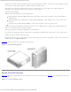
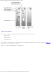
The cooling module is securely mounted to the power supply using a hook-and-latch fastener. This simplifies the removal and
installation of cooling modules and power supplies.
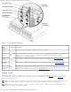
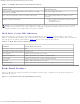
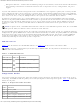
Table 1-7 lists the function of each power supply and cooling module LED indicator. See Figure 1-7 for the location of the LED
indicators.
Table 1-7. Power Supply/Cooling Module LED Indicators
Module
Icon
LED Indicator LED
Icon
Function
Power supply
Power on (green) DC output voltages are within specifications.
Fault (amber) One of the DC output voltages is not within specifications.
AC status (green) AC input voltage is within specifications regardless of the position of the
power switch.
Cooling
module
Blower A fault
(amber)
Cooling module blower A has failed.
Blower B fault
(amber)
Cooling module blower B has failed.
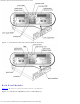
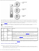
Figure 1-7. Power Supply and Cooling Module LED Features and Indicators