Dell PowerVault MD Storage Array vCenter Plug-in for VMware vSphere Installation and Configuration Guide
Notes, Cautions, and Warnings NOTE: A NOTE indicates important information that helps you make better use of your computer. CAUTION: A CAUTION indicates either potential damage to hardware or loss of data and tells you how to avoid the problem. WARNING: A WARNING indicates a potential for property damage, personal injury, or death. Copyright © 2014 Dell Inc. All rights reserved. This product is protected by U.S. and international copyright and intellectual property laws.
Contents 1 Overview......................................................................................................................7 Installation Prerequisites........................................................................................................................7 Configuration Limitations And Scalability............................................................................................ 8 Localization Support.....................................................................
Installing The SAS Provider (ESXi 5.0 and 5.1 Servers Only).........................................................33 Configuring SAS Support On ESX And ESXi Hosts.............................................................................34 Requirements For Using A SAS Host............................................................................................ 34 Creating A New User Login With Host Privileges (ESX And ESXi Servers)...................................
Testing Replication Communication............................................................................................69 Suspending Asynchronous Replication........................................................................................69 Resuming Replication................................................................................................................... 69 Changing Replication Roles.............................................................................................
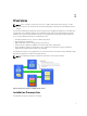
Overview 1 NOTE: Unless otherwise noted, later references to "MD Storage Array vCenter Plug-in" or "MD vCenter Plug-in" in this document are used interchangeably to represent the MD VMware vCenter Plug-in. The Dell PowerVault MD Storage Array vCenter Plug-in allows integrated management of Dell MD series storage arrays from a VMware vSphere client.
• VMware vCenter Server 5.x (installed on host server) • One of the following servers operating systems to host the application server: – Windows 2008 R2 SP1 Server – Windows Server 2012 – Windows Server 2012 R2 – Red Hat Enterprise Linux 5.9 or later (x64) – SUSE Enterprise Linux 11 or later (x64) • Make sure your MD storage has the latest RAID controller firmware version installed.
Upgrading From A Previous Version If you are upgrading from a previous version of the MD vCenter Plug-in but plan to use the same host server as the application server, run the latest installer on the current application server. The installation wizard will prompt for an administrator password before unregistering and upgrading your MD vCenter Plug-in version.
Installing The MD vCenter Plug-In NOTE: The MD vCenter Plug-in must be installed on the application server. If you downloaded the installer package to a different location, copy the installer files to the application server before performing the steps shown here. 1. From the application server launch the MD vCenter Plug-in installer, choose your language and click OK. 2. Review the copyright and introduction screens. To accept, click Next. 3. Read and accept the license agreement, then click Next. 4.
Configuring The Application Server And MD vCenter Plug-In 2 Once the application server and MD vCenter Plug-in are installed, verify that the MD vCenter Plug-in is successfully registered with the vCenter server: • Open the vSphere Client • From the vSphere Client menu bar, select Plug-ins → Manage Plug-ins • The Dell MD Storage Array vCenter Plug-in should be listed as Enabled If the MD vCenter Plug-in is listed as disabled with an error message indicating that it cannot communicate with the applic
5. Restart the Application Server service. NOTE: If the application server is reinstalled, this setting will be reverted to the original setting of 512 MB and must be edited again to adjust the application server memory for your environment. Figure 3. Configuring the Application Server Memory Configuring Storage Administrator Roles By default, any previously defined vCenter users will have no access to MD storage arrays.
Creating A Storage Administrator Role 1. In the Administration area on the vSphere Client home page, click Roles. A list of roles and usages is displayed. Figure 4. MD vCenter Plug-in Roles List 2. Click the Add Role icon in the menu bar, or right-click and select Add from the pop-up menu. The Add New Role is displayed.
Figure 5. Add New Role 3. In the Name text box, enter a name for the new role. 4. From the Privileges list, select the access permissions you want to assign to this role. NOTE: An administrator role is not editable. Therefore, if the administrator user will be used to manage storage, a new role must be created and all necessary privileges added to that role. The administrator user must then be added to this role, as described in the next section. 5.
6. When finished, click OK. NOTE: Existing non-administrator roles may be modified to include the new Storage Administrator privileges created. However, an existing administrator role cannot be modified. Adding An Existing User To The Storage Administrator Role Use these steps to add existing users to the Storage Administrator role you created previously. Storage Administrator roles can only be given to individual users, not to user groups. 1.
5. Click Add to select the users need access to the storage arrays. Figure 7. Assign Storage Administrator Role 6. Select the role you want to assign them from the drop-down box under Assigned Role. 7. Click OK to apply the permissions. Non-Authorized Plug-In Use Message When you create a new Storage Administrator role, you might have to restart the vSphere Client before the role is recognized. When this happens, a message similar to that shown in the figure Non-Authorized User Message is displayed.
Accepting And Installing The Trusted SSL Certificate During the vCenter Server installation process, an SSL certificate is generated for the vCenter Server system. If this certificate has not been added to the system's Trusted Root Certification Authorities (CA) store, a Security Alert dialog box is displayed when you start the MD vCenter Plug-in. Figure 9.
To avoid this message, you can import the install-generated certificate into the system's Trusted Root Certification Authorities store using the following steps. However, if CA-signed SSL certificates are not used, this alert message cannot be suppressed. 1. Click View Certificate. Figure 10. Install Certificate Dialog Box 2. 18 From the Certificate window, click Install Certificate.
3. In the Certificate Import Wizard, click Next. Figure 11. Select Certificate Store Dialog Box 4. From the Certificate Store window, select Place all certificates in the following store. 5. Click Browse. 6. In the Select Certificate Store window, highlight the Trusted Root Certification Authorities folder and click OK. 7. Click Next. 8. Click Finish. A Security Warning message box will be displayed.
9. Verify the information and click Yes to add the certificate to the trust store. Figure 12. Security Warning Message Box NOTE: The subject name of the system in the certificate must match the system name of the vCenter Server during the vSphere Client login screen. Otherwise, you will continue to receive warning messages that the certificate does not match the site name.
Figure 13. Microsoft Enhanced Security Message NOTE: If you are using the Save File option, you will also need to add the DNS name or IP address of the MD vCenter Plug-in application server in non-SSL format (for example, http://192.168.10.14) as a trusted site.
Figure 14. Microsoft Trusted Sites MD vCenter Plug-in Import And Export Configuration File The MD vCenter Plug-in provides the functionality to import or export the storage array manager configuration file, that maintains the list of configured storage arrays and metadata information. This feature is useful for backing up array configurations or deployment of new application server using an existing configuration file.
Application Server Login for Configuration File To access the import-export page on application server: 1. Open the web browser and enter the application server URL. For example:10.113.83.73:8084/vcenter2/ImportExportConfiguration.html A login page is displayed. 2. Enter the MD vCenter Plug-in login credentials. NOTE: The default login details are, User: admin and Password: admin. Figure 15. Login Page Exporting The Configuration File To export the current configuration file: 1.
4. Click the Import button. Figure 16. Importing and Exporting the Configuration File Application Server User Management The application server user management is controlled via the users.properties file located in C:\Program Files\Dell\MD Storage Array VMware vCenter Plug-In\jettydirectory. The format of the users.properties file is ID name, MD5 password hash, user ID. # #Thu Apr 11 18:02:33 PDT 2013 admin=MD5\:21232f297a57a5a743894a0e4a801fc3,admin ro=MD5\:3605c251087b88216c9bca890e07ad9c,storage.
Configuring The MD Storage Array For ESX/ESXi 3 The MD vCenter Plug-in allows an ESX/ESXi host to be automatically configured to use a Dell MD storage array by detecting the installed Host Bus Adapters (HBAs) within the host and configuring new hosts on the storage array with the Worldwide Names (WWNs) of the HBAs from the host. The default ESX/ESXi multi-pathing mode for Dell MD storage arrays is Most Recently Used (MRU).
Figure 17. Dual-Port HBA Configuration (Fibre Channel) This example shows a fully redundant fabric configuration. If a fibre channel switch or HBA fails, the alternate switch still connects both storage controllers in the storage array. If a storage controller also fails, the host can still access the remaining controller and all virtual disks fail over to that controller. A complete loss of access to storage occurs if any other element fails.
Figure 18.
Figure 19. Configuration Showing Double-Point Failure While this method works well in the case of hardware failure, MRU only maintains one active path for each HBA group. Therefore, if you have an ESX/ESXi host with four HBAs, only one HBA is active at a time. Grouping HBAs And Creating Virtual Hosts To achieve higher I/O throughput from the host to the storage array, group the HBAs in pairs and create virtual hosts for each pair of HBAs.
Figure 20. Four-Port HBA Configuration NOTE: The intent of this configuration is to pair the HBAs so that no group of HBA ports is contained on a single HBA card (if dual-port cards are used). For extending the configuration scheme, see the figure Eight-HBA Port Configuration.
Figure 21. Eight-HBA Port Configuration Configuring ALUA Support If your MD storage array firmware supports Asymmetric Logical Unit Access (ALUA), active-active throughput will enable LUN ownership to be transferred automatically to the alternate RAID controller in a failure event. Changing Your Default Multipath Policy Depending on your environment, you may be able to achieve higher performance by switching the default multipath policy from Most Recently Used (MRU) to Round Robin (RR).
• MD36xxi • MD36xxf This command: • Creates a new entry for the VMW_SATP_ALUA rule for any LUN matching the vendor and model ID (V DELL and -M array__model) you specified • Switches the default path selection policy to round robin (-P VMW_PSP_RR). NOTE: There are different methods to manage SATP claim rules. Your environment may require different parameters to enable ALUA support. Refer to the VMware Knowledge Base for additional information.
Figure 25. Adding Software iSCSI Adapter Network Configuration For MD-Series iSCSI Storage Arrays If you are using a Dell MD3600i-series or MD Dense iSCSI storage array with ESX/ESXi 4.x, run the following commands before mapping any virtual disks from the iSCSI storage array to the host.
3. From the shell prompt, enter vmware -v to verify the ESX version as 4.1. NOTE: If root is not enabled, log in as a shell-enabled user.4. Enter rpm -q lsi-provider. 4. For ESX/ESXi host version: a) Enter rpm -q lsi-provider for ESX hosts. b) Enter esxupdate --vib-view query | grep lsi-provider for ESXi hosts. The version listed is lsi-provider-410.04.V0.24-140815. 5. Enter esxupdate -b file:$PWD/vmware-esx4.1-SAS-provider.vib --nodeps --nosigcheck -maintenancemode update.
6. Reboot the host. 7. When the host reboot is complete, run esxcli software vib list | grep LSI to verify that the upgrade was successfully applied. Configuring SAS Support On ESX And ESXi Hosts To configure the MD vCenter Plug-in for ESX or ESXi hosts connecting to SAS-based Dell MD storage arrays, the SAS SMI-S provider must be upgraded on the host. NOTE: SAS is supported only on ESX/ESXi 4.1 or later hosts. Previous ESX/ESXi versions do not support SAS-based storage array connections.
Enabling Root Login From A Host Console (ESXi Servers Only) Follow the steps below to enable root login from an ESXi host. 1. Press F2 to switch to open the configuration menu. 2. Select Troubleshooting Options. 3. Select Enable Remote Tech Support. 4. Select Restart Management Agents. 5. Press Esc to close the Configuration menu.
Configuring The ESX/ESXi Host 4 To use the Automatic Host Configuration utility: 1. Navigate to Hosts and Clusters of the vSphere Client home page. 2. Select the host to be configured.
3. Right-click the host and select Configure ESX Host to Storage Array. Figure 26. ESX/ESXi Host Configuration Menu Configuring ESX Host To Storage Array The Configure ESX Host to Storage Array wizard allows you to see how the current host is configured to the storage array (if already configured). You can also use this wizard to add, remove or rename a host or host group, or automatically configure the host to another storage array.
Figure 27. Configure Host to Storage Array View This wizard walks you through the process of configuring HBAs on ESX/ESXi hosts to the storage arrays you configure in the plug-in array manager. It also provides additional information needed to detect and configure SAS HBAs on the ESX/ESXi hosts. NOTE: By default, the wizard will only display hosts that are prefixed with ESX_ and host groups prefixed with VMware_. To display others, select the Show all host groups as described in step 7. 1.
5. The Suggested Configuration page displays recommended HBA port configurations, host configuration and host group configurations. Suggested changes are displayed in blue italics (see Figure Suggested Host Configurations). – To accept the suggested configuration, click Next. Go to step 10 to complete the configuration. – To manually configure the host, select Use manual configuration and continue to step 6. Figure 28. Suggested Host Configurations 6.
11. Repeat steps 8 through 10 for each pair of HBAs to be used for the ESX host. Figure 29. Manually Adding a Host Dialog NOTE: The Configure ESX Host to Storage Array wizard does not detect how the fibre channel switch fabric is zoned. Suggested configurations are based on HBA ports detected and may require the fabric to be rezoned based on your specific environment cabling. You cannot rename or remove existing configured hosts or host groups.
Figure 30.
Managing Storage Arrays Using The MD vCenter Plug-In Manager View 5 This section describes how to use the storage array management features in the MD vCenter Plug-in. Before continuing, make sure you have configured your host and storage array as described in the preceding sections. Storage Array Manager Features To use the MD vCenter Plug-In to manage your storage arrays, click the MD vCenter Plug-in icon on the vSphere Client home page in the Solutions and Applications section.
To add a storage array using the MD vCenter Plug-in: 1. Click Add Array in the Commands area of the Array Manager view. Figure 31. Add Storage Array A dialog box is displayed showing DNS name/IP address text boxes for RAID Controller A and B, as well as a Password field. Figure 32. Add Storage Array Dialog 2. In Controller A (DNS or IPv4), enter the IP address or DNS name of RAID controller A on the storage array. 3.
5. Optionally, you can create unique asset tag keys and values for your storage arrays. For more information, see the topic Organizing Storage Arrays. 6. Click Add to add the storage arrays. 7. Click Close when all storage arrays are added. Discovering Storage Arrays To add a storage array to the vCenter Plug-in using automatic discovery: 1. In the Commands area of the Array Manager view, click Discover Arrays. 2.
Refresh Option The Refresh option in the storage manager view, displays the configured storage arrays for status changes. The storage array manager view automatically updates this view. Using Asset Tags Asset tags allow you to define custom characteristics for each storage array, such as city, state, row number and type. Once an asset tag key and value are assigned to a storage array, a storage panel can be created to automatically group all storage arrays matching the criteria specified for the panel.
Using a wildcard character (*) in an asset tag value, the folder display will automatically create sub folders based on the storage asset tag values as shown in figure. If you assign a specific value, no subfolders are created. Figure 35. Storage Array Panel Configuration with Specific Asset Tag Value Managing Asset Tags Asset tag keys and values can also be managed by selecting the Manage Tags link in the Commands area.
Asset tag keys and values must not be removed from individual storage arrays from this window. Removing Storage Arrays From The vCenter Plug-In Manager View Storage arrays may be removed by either selecting the individual storage array in the Array Manager Folder view or by selecting the All Storage Arrays object. Selecting the All Storage Arrays object will display a window of all storage arrays currently configured, that may be individually selected for removal.
Figure 38. Storage Array Table View Assigning Asset Tags And Values Asset tags are custom data tags that can be associated with each storage array. They provide a method for sorting and organizing storage arrays based on your environment and needs. To define and assign an asset tag value to a storage array: 1. Select a storage array in the All Storage Arrays list. 2. Click Edit in the Tag Assignments area. An Edit Storage Array window is displayed. Figure 39.
Changing The vCenter Plug-In Password Follow these steps to change the vCenter plug-in password: 1. Open the Array Manager View. 2. Click the name of the storage array in the left plane. 3. Click Edit Storage Array, in the right pane. The Edit Storage Array dialog box is displayed. 4. Enter the new vCenter Plug-in password in the Password field. 5. Click OK. 6. Click Verify Password, to verify that the password you entered matches the password on the storage array.
Figure 40. Summary Tab View Editing Storage Array Properties The Edit Storage Array feature on the Commands area allows you to change a storage array’s IP addresses, defines a password, verify the password entered matches the password configured on the storage array, and manage asset tag keys and values for selected storage array. Figure 41.
Storage Array Event Log The MD vCenter Plug-in allows you to view the Event Log for a storage array. NOTE: If the file is locked, you can create a copy of the file with a different name, then open the copied file. Accessing The Event Log To access the event log: 1. Click View Event Log in the storage array Summary window. You can set filters in the Event Log to show events (all or only critical), view details for a selected event and specify the number of events to retrieve.
or from MDSM. A storage array modification event will start a four-minute timer on the application server. If, within that four-minute time window, no other configuration events have occurred on the storage array, a save configuration will occur. If another modification event occurs within the four-minute time window, the timer resets to four minutes. When no modification events are detected on the storage array within the four-minute window, a save configuration will be performed.
3. In the right pane, click Manually Save Configuration. The Manually Save Configuration dialog box is displayed. Figure 44. Manually Save Configuration Message 4. Click OK. Internet explorer will launch a File Download dialog box. 5. If a security alert notifies you that you are leaving a secure Internet connection, click Yes. 6. If your security settings block you from downloading the file, add the non-secured HTTP address for your vCenter application server to your trusted sites list.
• Provide more flexibility for resizing Virtual Disks and performing snapshots. • Result in fewer VMFS datastores to manage. More, smaller virtual disks are appropriate for the following reasons: • Less wasted storage space. • Different applications might require different RAID characteristics. • Provide more flexibility, since the multi-pathing policy and disk shares are set per Virtual Disks. • Microsoft Cluster Service requires that each cluster disk resource is in its own Virtual Disks.
• Create/Disable/Recreate Snapshot • Delete Multiple Virtual Disks • Redistribute Virtual Disks Creating A Virtual Disks Group Selecting an object in the logical view will update the Capacity window in the lower right corner of the display to show available unconfigured, free and used capacity within the selected array. Before creating a disk group, decide from which available disk space you want to create the disk group.
3. As filtering criteria is entered, available physical disks are displayed in the table shown in the figure Create Virtual Disks Group Dialog. Use the checkbox on the left side of the window to select physical disks you want to include as part of the Virtual Disks group. 4. Click OK. Figure 46.
4. In the Capacity field, enter the size of the new Virtual Disks and select the modifier from the dropdown list. 5. In the I/O Settings field, select the segment size for the new Virtual Disks. 6. (Optional) Select the checkbox if multiple Virtual Disks are desired and then select the number of Virtual Disks to create. 7. (Optional) Select the Map now checkbox if the new Virtual Disks should be mapped immediately to a host or host group. 8. Click OK.
• Disable Snapshot – Disables the snapshot of a base virtual disk. • Recreate Snapshot – Recreates a disabled snapshot. NOTE: Legacy snapshots are not allowed on thin provisioned Virtual Disks. Creating A Legacy Snapshot The snapshot commands within the Virtual Disks view tab allows management of the legacy snapshot feature. Virtual Disks residing on disk pools do not support legacy snapshots. To create a snapshot of a Virtual Disks residing on a disk pool, use the new snapshot feature. 1.
Deleting Multiple Virtual Disks The Delete Multiple Virtual Disks command provides the ability to delete multiple Virtual Disks at one time. To delete multiple Virtual Disks: 1. Click the Delete Multiple Virtual Disks command. The Delete Multiple Virtual Disks dialog box is displayed. 2. Select the Virtual Disks to be deleted. 3. Click OK to delete the selected Virtual Disks. 4. Click OK on the confirmation dialog to confirm deletion of the selected Virtual Disks.
Mapping A Virtual Disks To Host To present a Virtual Disk to an ESX/ESXi host: 1. Select the host or host group to present the Virtual Disk to and then click Add Mapping command. Figure 48. Virtual Disk Mapping View 2. Select the Virtual Disks to be presented to the host or host group. 3. Accept the default logical unit number (LUN) for the selected Virtual Disks. 4. Click Add. Repeat steps 2 through 4 for additional Virtual Disks. 5. Click Close.
Figure 49. Storage Adapters Rescan From this view, the user can also verify that the correct number of paths have been configured. By rightclicking on one of the devices listed under the storage adapter and selecting Manage Paths, a window opens that shows the number of paths for the target device. There should be four paths to each device, two Active and two Standby. Figure 50.
Adding Host To Virtual Disks The Add Host command allows for defining hosts used to present Virtual Disks to. To add a new host: 1. Click the Add Host command. 2. Enter the name for the new host. 3. Select the host type from the drop-down box. 4. Select the interface type and click Next. 5. Select the available host port identifiers for the new host to be added. 6. Click the down arrow to move the host port identifier to the lower window.
Creating A New Virtual Disks Copy To create a new Virtual Disks copy: 1. Click Create Virtual Disks Copy in the Commands area. The Virtual Disks Copy wizard is displayed. Figure 51. Create Virtual Disk Copy Dialog 2. Select the source Virtual Disks and click Next. NOTE: While the Virtual Disks copy is being established, the source Virtual Disks is read-only to the host to which the Virtual Disks copy is presented.
3. Choose either Use existing Virtual Disks or Create a new Virtual Disks. Figure 52. Virtual Disk Copy Target Dialog 4. Select the copy priority to use while establishing the new Virtual Disks copy. 5. Click Next. 6. Verify the Virtual Disks copy settings and click Finish to start the Virtual Disks copy. Remove Copy Pair Command The Remove Copy Pair command removes the relationship of the source and target of a Virtual Disks copy pair.
Stop Virtual Disks Copy Command The Stop Virtual Disks Copy command provides the ability to abort a Virtual Disks copy operation that is in-progress. To stop a Virtual Disks copy: 1. Select an existing Virtual Disks copy pair that is in-progress. 2. Click Stop Virtual Disks Copy command. 3. Choose OK to stop the operation or Cancel to continue the Virtual Disks copy operation. Changing Virtual Disk Copy Parameters To change the target voume to read-write or change the modification priority: 1.
• Change Replication Parameters Figure 54. Synchronous Replication View Creating Remote Virtual Disks Replication The Create Remote Virtual Disks Replication command is used to establish a remote Virtual Disks replication between two storage arrays connected via fibre channel. To establish a new remote Virtual Disks replication: NOTE: To create remote replication, both storage arrays (local and remote) must be added to the Array Manager view. 1. Click the Create Synchronous Replication command. 2.
9. Review the Confirmation page, and click Finish to establish the replication relationship. Figure 55. Synchronous Remote Replication Confirmation Removing Replicated Pairs Removing a Replicated pair breaks the relationship between the primary and secondary Virtual Disks. Both Virtual Disks return to standard Virtual Disks status and no data is deleted. The replication relationship cannot be resumed after the operation starts. To remove a Replicated pair: 1.
4. Select the confirmation box. 5. Click OK. The Replicated pair is removed from the Replicated Pairs table. Testing Replication Communication Testing Replicated communication displays the round-trip times between the Virtual Disks in the Replicated pair. The times are displayed as average round-trip times, shortest round-trip times, and longest round-trip times. To test Replicated communication: 1. Click Test Replicated Communication in the Commands area.
• Demotes the primary Virtual Disks to the secondary Virtual Disks and disables writes to the Virtual Disks from the primary site. To change replication roles: 1. Select the Replicated pair from the Replicated Pairs window. 2. Click Change Replicated Roles command. 3. Choose OK to change the replication roles or Cancel to abort the operation.
Figure 58. PiT Snapshot View Creating Snapshot Group A snapshot group is used to hold snapshot images of a storage array Virtual Disks. To create a new snapshot group: 1. Select the base Virtual Disks from the Virtual Disks tree Window. 2. Click Create Snapshot Group command. 3. Modify the Base Virtual Disks and Snapshot Group Name parameters as required. 4. Click OK.
Creating A Snapshot Image A snapshot image is a point-in-time copy of the base Virtual Disks. Once a PiT-based snapshot image is created, it can be used to revert the base Virtual Disks to or may be used to create a Virtual Disks from.. To create a snapshot image: 1. Select the base Virtual Disks from the Virtual Disks tree window. 2. Click Create Snapshot Image command. Figure 59. Create Snapshot Image Dialog 3.
4. In the Snapshot Virtual Disks name box, enter a name for the snapshot Virtual Disks. Figure 60. Create Snapshot Virtual Disk 5. Select the Access mode for the snapshot virtual disk. 6. Click Finish. Changing Snapshot Settings The Change Settings command allows for modifying the selected snapshot group or snapshot Virtual Disks settings. To modify the settings of an existing snapshot group: 1. Expand the base Virtual Disks in the Virtual Disks tree window. 2.
Delete Command The Delete command allows for removal of snapshot Virtual Disks, snapshot images, or snapshot groups depending on the object select. The Delete option will open a dialog box of the selected object displaying the leafs of that object. To Delete a snapshot object, 1. Expand the base Virtual Disks from the Virtual Disks tree window. 2. Select either the Snapshot Groups, Snapshot Images, or Snapshot Virtual Disks object. 3. Click Delete command. 4.
Asynchronous Remote Replication The aRR feature is similar to RR by allowing source Virtual Disks from a primary storage array to be replicated to a target Virtual Disks on a remote storage array. However, aRR supports both iSCSI and fibre channel connections between the storage arrays and utilizes point-in-time replication strategy. aRR enables you to manage the synchronization process of creating a consistent data set on a remote storage array.
Creating Replicated Pairs The Create Replicated Pair option allows for creating a replication pair relationship between a primary Virtual Disks on the primary array and a secondary Virtual Disks on the secondary array. To create a new Replicated pair, perform the following: 1. In the Asynchronous Replication Groups table, select an ARG (with primary role) in which to create a Replicated pair. 2. Click Create Replicated Pair command. The Create Asynchronous Replicated Pair dialog is displayed. Figure 62.
6. Select Finish. The ARG table shows the status of the group as Initial Sync. Figure 63. Initial Sync Status Asynchronous Replication Groups Table and Replicated Pairs Table Changing Roles The Change Roles option promotes the current secondary replication group to the primary role and demotes the current primary replication group to the secondary role.
4. Click OK. Figure 64. Suspended Asynchronous Replication Group Resuming Replication Replication can be resumed only when all members of the asynchronous replication group are in the Optimal status. The resume operation can be performed only by the storage array that contains the virtual disk in the primary role for the ARR. Follow the steps below to resume replication: 1. Select the suspend ARR from the Asynchronous Replication Groups window. 2. Click Resume Replication command. 3.
To delete an asynchronous replication group : 1. In the All Storage Arrays table, select the storage array group from which an asynchronous replication group has to be deleted. 2. In the Asynchronous Replication Groups table, select an asynchronous replication group to delete. 3. Click Delete. The Delete Asynchronous Replication Group dialog box is displayed. Figure 65. Delete Remote Replication Group Dialog 4. Select the confirmation check box. 5. Click OK.
3. Click Remove Replicated Pair. The Remove Asynchronous Replication Group Member dialog is displayed. Figure 66. Remove Remote Replication Group Member Dialog 4. 5. Select the confirmation box. Click OK. The Replicated pair is removed from the Replicated Pairs table. Datastores View After datastores are created on storage array Virtual Disks, the Datastores View tab can be used to understand the mapping of datastores to storage array Virtual Disks.
Figure 67. Datastores View Manually Unregistering The MD vCenter Plug-In If the MD vCenter plug-in needs to be removed, the following procedure can be used when it is not possible to uninstall the plug-in from the application server. 1. From a browser, navigate to the IP address of the vCenter Server with /mob appended to the IP address (example: http://192.168.51.21/mob). 2. Click the content link to navigate to the available ServiceContent. 3.
6. Restart the vSphere Client to reflect the changes. Figure 68. Manually Unregister Extension Uninstall The MD vCenter Plug-In Uninstall the MD vCenter Plug-in using the uninstaller located on the application server at: C:\Program Files\Dell MD Storage Array vCenter Management Plug-in\Uninstall Dell MD Storage Array vCenter PlugIn\Uninstall Dell MD Storage Array vCenter Management Plug-in.exe.
Troubleshooting MD vCenter Plug-In Issues 6 This section describes how to open and read MD vCenter Plug-in log file, provides answers to some frequently asked questions, and describes how to resolve some common problems you might encounter with the MD vCenter Plug-in. Application Server Logs All procedures that are performed from the MD vCenter Plug-in are logged to the following file on the application server: C:\Program Files\Dell MD Storage Array vCenter Management Plug-in\jetty\logs\ vCenter2-logx.y.
I Cannot Communicate With The Application Server 1. Check the firewall settings to verify that the Jetty TCP port is enabled. If the Jetty TCP port is not enabled, enable it 2. Verify that the Jetty6-Service is started on the application server. If the Jetty6-Service is stopped, start it. NOTE: If the MD vCenter Plug-in will be installed on the same system as an active vCenter Server and VMware Update Manager is installed, port number 8084 for the plug-in must be changed to an unused port number.
a. Remove the storage array from the MD vCenter Plug-in. b. In MDSM, rename the storage array. c. Re-add the storage array to the MD vCenter Plug-in. Long Timeout For SAS ESX Host Wizard Operation When attempting to configure SAS HBAs on an ESX/ESXi host with unsupported SAS HBA cards, the wizard may not timeout after 15 minutes. To fix the issue, close and restart the vSphere Client.
Figure 70.
Getting Help 7 Related Documentation NOTE: For all PowerEdge documentation, go to www.dell.com/poweredgemanuals and enter the system Service Tag to get your system documentation. NOTE: For all PowerVault documentation, go to www.dell.com/powervaultmanuals and enter the system Service Tag to get your system documentation. NOTE: For Dell Support Forums, go to en.community.dell.com/support-forums/default.aspx. NOTE: For Dell Advanced Search , go to search.dell.com/index.aspx.
5. 88 Choose your preferred method of contact.