Dell PowerVault MD3800f and MD3820f Storage Arrays Owner's Manual Regulatory Model: E03J and E04J Series Regulatory Type: E03J001 and E04J001
Notes, Cautions, and Warnings NOTE: A NOTE indicates important information that helps you make better use of your computer. CAUTION: A CAUTION indicates either potential damage to hardware or loss of data and tells you how to avoid the problem. WARNING: A WARNING indicates a potential for property damage, personal injury, or death. Copyright © 2014 Dell Inc. All rights reserved. This product is protected by U.S. and international copyright and intellectual property laws.
Contents 1 About Your System....................................................................................................7 Introduction........................................................................................................................................... 7 Front-Panel Features and Indicators.................................................................................................... 7 Back-Panel Features and Indicators........................................................
Installing a Physical Drive Into a Physical-Drive Carrier.............................................................. 24 RAID Controller Module .....................................................................................................................24 Removing a RAID Controller Module Blank................................................................................. 25 Installing a RAID Controller Module Blank.................................................................................
Noncritical Conditions.................................................................................................................. 45 Invalid Storage Array..................................................................................................................... 45 ECC Errors..................................................................................................................................... 45 PCI Errors.........................................................................
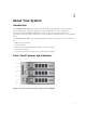
About Your System 1 Introduction The MD3800f and MD3820f Series storage array is designed for high availability, offering redundant access to data storage. Its features support both single and dual RAID controller configurations. The Dell PowerVault MD3800f and MD3820f Series storage array provides Fibre Channel (FC) connectivity to the host server. It enables access for up to eight non-redundant servers or four redundant servers.
Figure 2. Front-Panel Features and Indicators—Dell PowerVault MD3820f Figure 3. Front-Bezel Features and Indicators Item Indicator, Button, or Connector Description 1 Enclosure status LED The enclosure status LED lights when the enclosure power is on. Lights blue during normal operation. Blinks blue when a host server is identifying the enclosure or when the system identification button is pressed.
Item Indicator, Button, or Connector Description Lights amber as enclosure boots or is reset. Blinks amber when the enclosure is either in a fault state or the hosts are not using the preferred path to a virtual disk. 2 Power LED The power LED lights green when at least one power supply is supplying power to the enclosure. 3 Split mode LED This LED must be unlit as the split mode function is not supported by the MD3800f Series Storage Arrays.
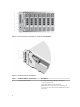
Back-Panel Features and Indicators Figure 4. Back-Panel Features and Indicators—Dell PowerVault MD3800f and MD3820f Series 1. 3. 600 W power supply/cooling fan RAID Controller Module 1 2. 4. RAID Controller Module 0 600 W power supply/cooling fan Physical-Drive Indicator Patterns Figure 5. Physical-Drive Indicators 1. physical-drive activity indicator (green) 2.
Drive-Status Indicator Pattern Condition (RAID Only) Blinks green, amber, and turns off Predicted drive failure Blinks amber four times per second Drive failed Blinks green slowly Drive rebuilding Steady green Drive online Blinks green three seconds, amber three seconds, and turns off six seconds Rebuild aborted Power Supply and Cooling Fan Features The MD3800f and MD3820f Series storage array includes two integrated, hot-swappable power supply/ cooling fan modules.
Item LED Type Icon Description If this LED is off, it indicates that the DC output voltage are not within the limit. 2 Power supply/ cooling fan fault The LED lights amber when the DC output voltage is not within the limit or a fault with the fan is detected. If this LED is off, it indicates that no fault condition is present. 3 AC power The LED lights green when the AC input voltage is within the limit.
Controller Modules 2 RAID Controller Modules The RAID controller modules provide high-performance, advanced virtual disk configuration, and faulttolerant disk subsystem management. Each RAID controller module contains 4GB or 8GB of mirrored cache for high availability and a battery-powered cache offload mechanism. NOTE: The 8GB mirrored cache is an optional feature.
Item Component Function 1 16 Gbps FC IN port (4) Provides host-to-controller FC connection. 2 Seven segment display sequence Displays status or error codes for the storage array. 3 Controller power LED Lights green when controller power is on. Turns off when controller is not powered. 4 Controller fault LED Lights amber when controller fault is detected.
RAID Controller Module—Additional Features Battery Backup Unit Each RAID controller contains a two-cell Lithium ion nanopolymer battery backup unit (BBU). It provides power to the RAID controller module in the event of a power outage. For information on removing and installing the BBU, see RAID Controller Module Backup Battery Unit . NOTE: For virtual disks, the RAID controller firmware changes the data cache setting based on the state of the battery.
Write-Back Cache In write-back cache, write operations result in a completion signal being sent to the host operating system as soon as the cache receives the data to be written. The target physical disk receives the data at a more appropriate time to increase controller performance. In dual-active controller configurations with write-back caching enabled, the write data is always mirrored to the cache of the second controller before completion status is issued to the host initiator.
Figure 9. SAS Cable 1. 3. mini SAS connector mini SAS HD connector 2. SAS cable Interoperability of 4 Gbps, 8 Gbps, and 16 Gbps Devices The FC standard specifies a procedure for speedy autodetection. If an 8 Gbps port on a switch or device is connected to a 4 Gbps port, it must negotiate down for the link to run at 4 Gbps. If there are two 16 Gbps ports on either end of a link, the negotiation runs the link at 16 Gbps if the link supports the required specifications.
Installing Array Components 3 Recommended Tools You may need the following items to perform the procedures in this section: • Key to the system keylock • #2 Phillips screwdriver • Wrist grounding strap Front Bezel (Optional) Removing the Front Bezel 1. Using the system key, unlock the front bezel (if locked). 2. Lift the release latch next to the keylock. 3. Rotate the left end of the bezel away from the front panel. 4.
3. Secure the bezel with the keylock. Physical Drives SAFETY Models AMT E03J and E04J Models AMT, E03J, and E04J are intended for installation only in restricted access locations as defined in cl 1.2.7.3 of IEC 60950-1:2005. Depending on your configuration, your array either supports up to twenty-four 2.5-inch SAS physical drives or up to twelve 3.5-inch SAS physical drives in internal drive bays.
Figure 12. Removing and Installing a 3.5 Inch Hard-Drive Blank (MD3800f only) 1. physical-drive blank 2. release button Installing a 3.5 Inch Physical-Drive Blank 1. If installed, remove the front bezel. 2. Insert the physical-drive blank into the physical-drive slot until the release button clicks into place. 3. If applicable, install the front bezel. Removing a Hot-Swap Physical Drive CAUTION: To prevent data loss, ensure that your operating system supports hot-swap drive installation.
Figure 13. Removing and Installing a Hot-Swap Physical Drive 1. 3. release button physical-drive carrier handle 2. physical drive Installing a Hot-Swap Physical Drive CAUTION: Many repairs may only be done by a certified service technician. You should only perform troubleshooting and simple repairs as authorized in your product documentation, or as directed by the online or telephone service and support team. Damage due to servicing that is not authorized by Dell is not covered by your warranty.
Removing a Physical Drive From a Physical-Drive Carrier 1. Remove the screws from the slide rails on the physical-drive carrier. 2. Lift the physical drive out of the physical-drive carrier. Figure 14. Removing and Installing a Physical Drive Into a 2.5 inch Physical-Drive Carrier 1. 3. physical-drive carrier screws (4) 2.
Figure 15. Removing and Installing a 3.5 Inch Physical Drive Into a Physical-Drive Carrier 1. 3. physical-drive carrier screws (4) 2. physical drive Installing a Physical Drive Into a Physical-Drive Carrier CAUTION: Many repairs may only be done by a certified service technician. You should only perform troubleshooting and simple repairs as authorized in your product documentation, or as directed by the online or telephone service and support team.
CAUTION: RAID controller modules can be removed and installed without turning off the array. It is recommended that you do not remove the RAID controller module while data is being transferred. Replacing or installing a RAID controller module that is connected to a host server causes it to lose communication with the array and may require a reboot of the host server.
CAUTION: If your configuration uses fiber-optic cables, remember that they are fragile. Bending, twisting, folding, or pinching fiber-optic cables can cause damage to the cables, degraded performance, or loss of data. To prevent damage, do not twist, fold, pinch, or step on the cables. Do not bend the cables in less than a 5 cm (2 inch) radius. 1. If small form-factor pluggable (SFP) transceivers are present, record the ports in which they are installed, and remove them. 2.
CAUTION: Many repairs may only be done by a certified service technician. You must only perform troubleshooting and simple repairs as authorized in your product documentation, or as directed by the online or telephone service and support team. Damage due to servicing that is not authorized by Dell is not covered by your warranty. Read and follow the safety instructions that came with the product. 1. Insert the RAID controller module into the RAID controller module bay until it seats into place. 2.
Closing the RAID Controller Module CAUTION: Many repairs may only be done by a certified service technician. You must only perform troubleshooting and simple repairs as authorized in your product documentation, or as directed by the online or telephone service and support team. Damage due to servicing that is not authorized by Dell is not covered by your warranty. Read and follow the safety instructions that came with the product. 1.
6. Slide the backup battery unit and lift it out of the RAID controller module. Figure 19. Removing and Installing the RAID Controller Module Backup Battery Unit 1. backup battery unit 2. screw Installing the RAID Controller Module Backup Battery Unit CAUTION: Many repairs may only be done by a certified service technician. You must only perform troubleshooting and simple repairs as authorized in your product documentation, or as directed by the online or telephone service and support team.
Removing a Power Supply/Cooling Fan Module CAUTION: Many repairs may only be done by a certified service technician. You must only perform troubleshooting and simple repairs as authorized in your product documentation, or as directed by the online or telephone service and support team. Damage due to servicing that is not authorized by Dell is not covered by your warranty. Read and follow the safety instructions that came with the product.
Installing a Power Supply/Cooling Fan Module CAUTION: Many repairs may only be done by a certified service technician. You must only perform troubleshooting and simple repairs as authorized in your product documentation, or as directed by the online or telephone service and support team. Damage due to servicing that is not authorized by Dell is not covered by your warranty. Read and follow the safety instructions that came with the product. 1.
4. Slide the control panel out of the chassis after: – Pushing the release tab toward the front of the array in PowerVault MD3800f. – Pulling the release pin toward the front of the array in PowerVault MD3820f. Figure 22. Removing and Installing the Control Panel—PowerVault MD3800f 1. control panel 2. release tab Figure 23. Removing and Installing the Control Panel—PowerVault MD3820f 1. release pin 2. control panel Installing the Control Panel 1.
3. Replace the hard drives in their respective slots. 4. Connect all the power cables to the array. 5. Turn on the array and the host server. Backplane Removing the Backplane CAUTION: Many repairs may only be done by a certified service technician. You must only perform troubleshooting and simple repairs as authorized in your product documentation, or as directed by the online or telephone service and support team. Damage due to servicing that is not authorized by Dell is not covered by your warranty.
11. Remove the screws that secure the backplane and pull the backplane out of the array. Figure 24. Removing and Installing the RAID Controller Module/Power Supply Cage 1. screws (6) 2. RAID controller module/power supply cage Figure 25. Removing and Installing the Backplane—PowerVault MD3800f 1. 3. 34 screws (5) captive screw 2.
Figure 26. Removing and Installing the Backplane—PowerVault MD3820f 1. 3. screws (4) captive screw 2. backplane Installing the Backplane 1. Align the screw holes on the backplane with the screw holes on the array. 2. Tighten the captive screw to secure the backplane to the chassis. 3. Replace the screws that secure the backplane to the chassis. 4. Align the slots on the RAID controller module/power supply cage with the tabs on the chassis. 5.
Troubleshooting Your System 4 Safety First—For You and Your System CAUTION: Many repairs may only be done by a certified service technician. You should only perform troubleshooting and simple repairs as authorized in your product documentation, or as directed by the online or telephone service and support team. Damage due to servicing that is not authorized by Dell is not covered by your warranty. Read and follow the safety instructions that came with the product.
NOTE: Equip yourself with antistatic protection and a replacement small form-factor pluggable (SFP) transceiver before replacing an SFP transceiver in the RAID controller module. Also, see the initial setup information for the enclosure to verify LED definitions. CAUTION: To prevent degraded performance, do not twist, fold, pinch, or step on fibre optic cables. Do not bend the fibre optic cables tighter than a 5 cm (2 inch) radius. 1.
7. Install the new SFP transceiver into the interface port. Ensure that the transceiver is properly seated. 8. Reconnect the fiber optic cable. 9. View the FC IN speed LEDs and the Physical Disk Channel speed LEDs. Based on the LED status, perform one of these actions: – If at least one of the FC IN LEDs for each port is on, go to step 11. – Both the FC IN LEDs on an MD storage array RAID controller module enclosure for a particular port are off. – Check that the SFP transceiver is installed correctly.
CAUTION: It is recommended that you turn off the host server before turning off the array to prevent loss of data. 1. Locate the faulty power supply and determine the status of the LEDs. – If the AC power LED is not lit, check the power cord and power source into which the power supply module is plugged. * Connect another device to the power source to verify if it is working. * Connect the cable to a different power source. * Replace the power cable. If the problem is not resolved, see Getting Help.
If EMM Status LED is Blinking Amber (5 Times per Sequence) Update the firmware to the latest supported firmware on both the EMMs. For more information on updating your EMM firmware, see Management Firmware Downloads in the Storage Arrays Administrator's Guide at dell.com/powervaultmanuals. If the EMM Status LED is Solid or Blinking Amber (2 or 4 Times per Sequence) 1. Turn off the host server. 2. Remove the EMM and verify that the pins on the backplane and EMM are not bent. 3.
4. Remove the RAID controller module and verify that the pins on backplane and RAID controller module are not bent. 5. Reinstall the RAID controller module and wait for 30 seconds. 6. Check the RAID controller module status LED. 7. Replace the RAID controller module. 8. Turn on the host server. If the problem is not resolved, see Getting Help. If Both LEDs for any Given FC IN Port are Unlit 1. Turn off the host server, storage arrays, and expansion enclosures. 2.
Troubleshooting Array and Expansion Enclosure Connections 1. Verify the following: – the SAS OUT status LED is green – for each FC IN port connected to a cable, at least one of the paired LEDs is on 2. Ensure that all the cables are attached correctly according to the array mode you selected. 3. Turn off the host server, storage array, and expansion enclosures. 4. Reseat the RAID controller module and reconnect cables on the storage array and the host server. 5.
6. Close the system. 7. Turn on the system and attached peripherals. If the system does not start properly, see Getting Help. 8. If the system starts properly, shut down the system and reinstall all of the expansion cards that you removed. 9. Run the appropriate diagnostic test. For more information, see Using System Diagnostics. If the tests fail, see Getting Help. Troubleshooting a Damaged System CAUTION: Many repairs may only be done by a certified service technician.
Critical Conditions The storage array generates a critical event if the RAID controller module detects a critical condition that could cause immediate failure of the array and/or loss of data.
Technical Specifications 5 Physical Disks Physical disks Up to twelve 3.5 inch or twenty-four 2.5 inch SAS, nearline SAS physical disks, or SAS SSDs RAID Controller Modules RAID controller modules Two hot-swappable modules with temperature sensors 4GB or 8GB of cache per controller Provides host-to-controller 16G FC connection Expansion Modules Dell PowerVault MD1200 and MD1220 expansion enclosures Each expansion enclosure holds Up to twelve 3.5 inch or twenty-four 2.
Back-Panel Connectors (Per RAID Controller Module) Serial connector (debug port) One mini-USB port NOTE: For technical support use only. Management Ethernet connector One 100/1000 Mbps Ethernet connection for out-ofband management of the enclosure (MGMT) Power AC power supply (per power supply) Wattage 600 W Heat dissipation (maximum) 100 W NOTE: Heat dissipation is calculated using the power supply wattage rating.
Environmental Operating 10% to 80% (noncondensing) with maximum humidity gradation of 10% per hour Storage 5% to 95% at a maximum wet bulb temperature of 33 °C (91 °F) Maximum vibration Operating 0.26 Grms at 5 Hz to 350 Hz in operational orientation Storage 1.88 Grms at 10 Hz to 500 Hz for 15 minutes (all six sides tested) Maximum shock Operating One shock pulse in the positive z axis of the system at 31 G for 2.
Getting Help 6 Locating Your System Service Tag Your system is identified by a unique Express Service Code and Service Tag number. The Express Service Code and Service Tag are found on the front of the system by pulling out the information tag. This information is used by Dell to route support calls to the appropriate personnel. Contacting Dell NOTE: If you do not have an active Internet connection, you can find contact information on your purchase invoice, packing slip, bill, or Dell product catalog.