Dell EMC PowerVault MD3800i and MD3820i Storage Arrays Owner's Manual Regulatory Model: E03J and E04J Series Regulatory Type: E03J001 and E04J001 July 2018 Rev.
Notes, cautions, and warnings NOTE: A NOTE indicates important information that helps you make better use of your product. CAUTION: A CAUTION indicates either potential damage to hardware or loss of data and tells you how to avoid the problem. WARNING: A WARNING indicates a potential for property damage, personal injury, or death. © 2015 - 2018 Dell Inc. or its subsidiaries. All rights reserved. Dell, EMC, and other trademarks are trademarks of Dell Inc. or its subsidiaries.
Contents Chapter 1: About Your System.......................................................................................................5 Introduction...........................................................................................................................................................................5 Front-Panel Features and Indicators..............................................................................................................................
Removing the RAID Controller Module Backup Battery Unit .......................................................................... 23 Installing the RAID Controller Module Backup Battery Unit..............................................................................23 Power Supply or Cooling Fan Module.......................................................................................................................... 24 Removing a Power Supply or Cooling Fan Module...................................
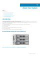
1 About Your System Topics: • • • • • • • Introduction Front-Panel Features and Indicators Back-Panel Features and Indicators Physical-Drive Indicator Patterns Power Supply and Cooling Fan Features Power Indicator Codes and Features Related Documentation Introduction The MD3800i and MD3820i Series storage array is designed for high availability, offering redundant access to data storage. Its features support both single and dual RAID controller configurations.
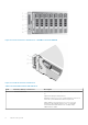
Figure 2. Front-Panel Features and Indicators—Dell EMC PowerVault MD3820i Figure 3. Front-Bezel Features and Indicators Table 1. Front-Panel Features and Indicators Item Indicator, Button, or Connector Description 1 Enclosure status LED The enclosure status LED lights when the enclosure power is on. Lights blue during normal operation. Blinks blue when a host server is identifying the enclosure or when the system identification button is pressed. Lights amber as enclosure boots or is reset.
Table 1. Front-Panel Features and Indicators (continued) Item Indicator, Button, or Connector Description Blinks amber when the enclosure is either in a fault state or the hosts are not using the preferred path to a virtual disk. For more information about diagnosing the issue, see Dell EMC PowerVault MD 34XX/38XX Series Storage Arrays Administrator's Guide. 2 Power LED The power LED lights green when at least one power supply is supplying power to the enclosure.
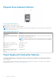
Physical-Drive Indicator Patterns Figure 5. Physical-Drive Indicators 1. physical-drive activity indicator (green) 2. physical-drive status indicator (green and amber) NOTE: If the physical drive is in Advanced Host Controller Interface (AHCI) mode, the status indicator (on the right side) does not function and remains off. Table 2.
Power Indicator Codes and Features Figure 6. Power Indicator Codes and Features Table 3. Power Indicator Codes and Features Item LED Type 1 DC power Icon Description The LED lights green when the DC output voltage is within the limit. If this LED is off, it indicates that the DC output voltage are not within the limit. 2 Power supply/ cooling fan fault The LED lights amber when the DC output voltage is not within the limit or a fault with the fan is detected.
● Dell EMC PowerVault Modular Disk Storage Arrays CLI Guide — Provides information about configuring and managing the system using the MDSM CLI. ● Dell EMC PowerVault MD3800i and MD3820i Storage Arrays Deployment Guide — Provides information about deploying the storage system in the SAN architecture. ● Dell EMC PowerVault MD34xx and 38xx Series Support Matrix — Provides information about the software and hardware compatibility matrices for the storage array.
2 Controller Modules Topics: • • • • RAID Controller Modules RAID Controller Module Connectors And Features RAID Controller Module—Additional Features Cache Functions and Features RAID Controller Modules The RAID controller modules provide high-performance, advanced virtual disk configuration, and fault-tolerant disk subsystem management. Each RAID controller module contains 4GB or 8GB of mirrored cache for high availability and a battery-powered cache offload mechanism.
Table 4. RAID Controller Module Connectors And Features (continued) Item Component Function 2 Seven segment display sequence Displays status or error codes for the storage array. 3 Controller power LED Lights green when controller power is on. Turns off when controller is not powered. 4 Controller fault LED Lights amber when controller fault is detected. Turns off when controller is operating normally.
NOTE: For virtual disks, the RAID controller firmware changes the data cache setting based on the state of the battery. If the battery is missing or does not have sufficient charge, the controller flushes the cache and sets the write cache attribute to Write Through for all virtual disks. When the battery is replaced, Write Back is re-enabled. Storage Array Thermal Shutdown The system automatically shuts down when system temperature exceeds the safe threshold.
The RAID controller automatically switches to write-through if cache mirroring is disabled, or if the battery is missing, or has a fault condition.
3 Installing Array Components Topics: • • • • • • • • Recommended Tools Front Bezel (Optional) Physical Drives RAID Controller Module RAID Controller Module Backup Battery Unit Power Supply or Cooling Fan Module Control Panel Backplane Recommended Tools You may need the following items to perform the procedures in this section: ● Key to the system keylock ● #2 Phillips screwdriver ● Wrist grounding strap Front Bezel (Optional) Removing the Front Bezel 1.
3. release latch 4. hinge tab Installing the Front Bezel 1. Hook the right end of the bezel onto the chassis. 2. Fit the free end of the bezel onto the system. 3. Secure the bezel with the keylock. Physical Drives SAFETY Models AMT E03J and E04J Models AMT, E03J, and E04J are intended for installation only in restricted access locations as defined in cl 1.2.7.3 of IEC 60950-1:2005. Depending on your configuration, your array either supports up to twenty-four 2.
Removing a 3.5 Inch Physical-Drive Blank CAUTION: To maintain proper system cooling, all empty hard-drive slots must have drive blanks installed. 1. If installed, remove the front bezel. 2. Press the release button and slide the physical-drive blank out until it is free from the physical-drive slot. Figure 10. Removing and Installing a 3.5 Inch Hard-Drive Blank (MD3800i only) 1. physical-drive blank 2. release button Installing a 3.5 Inch Physical-Drive Blank 1. If installed, remove the front bezel. 2.
Figure 11. Removing and Installing a Hot-Swap Physical Drive 1. release button 2. physical drive 3. physical-drive carrier handle Installing a Hot-Swap Physical Drive CAUTION: Many repairs may only be done by a certified service technician. You should only perform troubleshooting and simple repairs as authorized in your product documentation, or as directed by the online or telephone service and support team. Damage due to servicing that is not authorized by Dell is not covered by your warranty.
Figure 12. Removing and Installing a Physical Drive Into a 2.5 inch Physical-Drive Carrier a. physical-drive carrier b. physical drive c. screws (4) Figure 13. Removing and Installing a 3.5 Inch Physical Drive Into a Physical-Drive Carrier a. physical-drive carrier b. physical drive c.
Installing a Physical Drive Into a Physical-Drive Carrier CAUTION: Many repairs may only be done by a certified service technician. You should only perform troubleshooting and simple repairs as authorized in your product documentation, or as directed by the online or telephone service and support team. Damage due to servicing that is not authorized by Dell is not covered by your warranty. Read and follow the safety instructions that are shipped with your product. 1.
Installing a RAID Controller Module Blank 1. Align the blank with the RAID controller module bay. 2. Insert the blank into the chassis until it clicks into place. Removing a RAID Controller Module CAUTION: Many repairs may only be done by a certified service technician. You must only perform troubleshooting and simple repairs as authorized in your product documentation, or as directed by the online or telephone service and support team.
4. If applicable, update the firmware for the RAID controller module. For information about the latest firmware, see dell.com/ support. Opening the RAID Controller Module CAUTION: Many repairs may only be done by a certified service technician. You must only perform troubleshooting and simple repairs as authorized in your product documentation, or as directed by the online or telephone service and support team. Damage due to servicing that is not authorized by Dell EMC is not covered by your warranty.
RAID Controller Module Backup Battery Unit Removing the RAID Controller Module Backup Battery Unit CAUTION: Many repairs may only be done by a certified service technician. You must only perform troubleshooting and simple repairs as authorized in your product documentation, or as directed by the online or telephone service and support team. Damage due to servicing that is not authorized by Dell EMC is not covered by your warranty. Read and follow the safety instructions that came with the product. 1.
Power Supply or Cooling Fan Module NOTE: Your storage array includes two integrated, hot-swappable power supply/cooling fan modules. The array supports two hot-swappable power supply/cooling fan modules. While the array can operate temporarily with one module, both the modules must be present for proper system cooling. CAUTION: A single power supply/cooling fan module can be removed from a powered-on array for a maximum period of 5 minutes.
telephone service and support team. Damage due to servicing that is not authorized by Dell EMC is not covered by your warranty. Read and follow the safety instructions that came with the product. 1. Slide the power supply/cooling fan module into the chassis until it is fully seated and the release tab clicks into place. 2. Connect the power cable to the power supply/cooling fan module and plug the cable into a power outlet. 3. Secure the power cable using the strap. Figure 19. Securing the power cable a.
Figure 20. Removing and Installing the Control Panel—PowerVault MD3800i a. control panel b. release tab Figure 21. Removing and Installing the Control Panel—PowerVault MD3820i a. release pin b. control panel Installing the Control Panel 1. Align the control panel with the slot on the array. 2. Slide the control panel into the array until: ● The release tab clicks into place in PowerVault MD3800i. ● The release pin clicks into place in PowerVault MD3820i. 3.
Backplane Removing the Backplane CAUTION: Many repairs may only be done by a certified service technician. You must only perform troubleshooting and simple repairs as authorized in your product documentation, or as directed by the online or telephone service and support team. Damage due to servicing that is not authorized by Dell EMC is not covered by your warranty. Read and follow the safety instructions that came with the product. 1. Turn off the array, and disconnect it from the electrical outlet. 2.
Figure 23. Removing and Installing the Backplane—PowerVault MD3800i a. screws (5) b. backplane c. captive screw Figure 24. Removing and Installing the Backplane—PowerVault MD3820i a. screws (4) b. backplane c. captive screw Installing the Backplane 1. Align the screw holes on the backplane with the screw holes on the array. 2. Tighten the captive screw to secure the backplane to the chassis. 3. Replace the screws that secure the backplane to the chassis. 4.
4 Troubleshooting Your System Safety First—For You and Your System CAUTION: Many repairs may only be done by a certified service technician. You should only perform troubleshooting and simple repairs as authorized in your product documentation, or as directed by the online or telephone service and support team. Damage due to servicing that is not authorized by Dell is not covered by your warranty. Read and follow the safety instructions that are shipped with your product.
Troubleshooting Power Supply or Cooling Fan Modules CAUTION: Many repairs may only be done by a certified service technician. You should only perform troubleshooting and simple repairs as authorized in your product documentation, or as directed by the online or telephone service and support team. Damage due to servicing that is not authorized by Dell is not covered by your warranty. Read and follow the safety instructions that are shipped with your product.
CAUTION: It is recommended that you turn off the host server before turning off the expansion enclosure array to prevent loss of data. If EMM Status LED is Blinking Amber at Five Times per Sequence Update the firmware to the latest supported firmware on both the EMMs. For more information on updating your EMM firmware, see Management Firmware Downloads in the Storage Arrays Administrator's Guide at dell.com/powervaultmanuals.
7. Replace the RAID controller module. 8. Turn on the host server. If the problem is not resolved, see Getting Help. If the Link Status LEDs are not Green 1. Turn off the host server. 2. Reseat the cables on the expansion array and the server. 3. Turn on the expansion arrays and the storage array and wait until the system is fully booted. 4. Turn on the host server. 5. Check the link status LED. If the link status LED is not green, replace the cables. If the problem is not resolved, see Getting Help.
Troubleshooting a Wet System CAUTION: Many repairs may only be done by a certified service technician. You should only perform troubleshooting and simple repairs as authorized in your product documentation, or as directed by the online or telephone service and support team. Damage due to servicing that is not authorized by Dell is not covered by your warranty. Read and follow the safety instructions that are shipped with your product. 1.
5. Close the system. 6. Run the appropriate diagnostic test. For more information, see Using System Diagnostics. If the tests fail, see Getting Help. Controller failure conditions Certain events can cause a RAID controller module to fail and/or shut down. Unrecoverable ECC memory or PCI errors, or critical physical conditions can cause lockdown. If your RAID storage array is configured for redundant access and cache mirroring, the surviving controller can normally recover without data loss or shutdown.
PCI errors The storage array firmware can detect and only recover from PCI errors when the RAID controller modules are configured for redundancy. If a virtual disk uses cache mirroring, it fails over to its peer RAID controller module, which initiates a flush of the dirty cache.
5 Technical Specifications Table 6. Physical Disks Physical disks Up to twelve 3.5 inch or twenty-four 2.5 inch SAS, nearline SAS physical disks, or SAS SSDs Table 7. RAID Controller Modules RAID controller modules Two hot-swappable modules with temperature sensors 4GB or 8GB of cache per controller Provides host-to-controller iSCSI 10 Gbps Ethernet connection Table 8. Expansion Modules Dell EMC PowerVault MD1200 and MD1220 expansion enclosures Each expansion enclosure holds Up to twelve 3.
Table 10. Power (continued) NOTE: Heat dissipation is calculated using the power supply wattage rating. The heat dissipation values are for the entire system which includes chassis and two controllers. Voltage NOTE: This system is also designed to be connected to IT power systems with a phase to phase voltage not exceeding 230 V. Battery 100–220 V AC, (8.6 A-4.3 A) 6.6 V DC, 1100 mAh, 7.26 W Lithium ion battery Table 11.
Table 12. Particulate Contamination NOTE: This section defines the limits to help avoid IT equipment damage and/or failure from particulates and gaseous contamination. If it is determined that levels of particulates or gaseous pollution are beyond the limits specified below and are the reason for the damage and/or failures to your equipment, it may be necessary for you to re-mediate the environmental conditions that are causing the damage and/or failures.
6 Getting help Topics: • • • Locating your system Service Tag Contacting Dell Documentation feedback Locating your system Service Tag Your system is identified by a unique Express Service Code and Service Tag number. The Express Service Code and Service Tag are found on the front of a physical DR Series system by pulling out the information tag. The service tag can also be found on the Support page in the GUI. This information is used to route support calls to the appropriate personnel for resolution.