Dell FluidFS NAS Solutions Owner's Manual Regulatory Model: E02T and C11M Regulatory Type: E02T001 and C11M001
Notes, Cautions, and Warnings NOTE: A NOTE indicates important information that helps you make better use of your computer. CAUTION: A CAUTION indicates either potential damage to hardware or loss of data and tells you how to avoid the problem. WARNING: A WARNING indicates a potential for property damage, personal injury, or death. © 2012 Dell Inc.
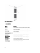
Contents Notes, Cautions, and Warnings...................................................................................................2 1 About Your System......................................................................................................................5 Front-Panel Features And Indicators.......................................................................................................................5 Back-Panel Features And Indicators............................................
Installing The Front LED Status Module...........................................................................................................27 Power Transmission Board Assembly....................................................................................................................27 Removing The Power Transmission Board Assembly.....................................................................................27 Installing The Power Transmission Board Assembly..............................
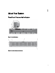
About Your System 1 Front-Panel Features And Indicators Figure 1. Front Bezel Indicators Figure 2.
Item Indicator, Button, or Connector Icon Description 1 System identification button The identification buttons on the front and back panels can be used to locate a particular system within a rack. When one of these buttons is pressed, the system status indicator on the back flashes until one of the buttons is pressed again. Press to toggle the system ID on and off.
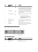
Item Indicator, Button, or Connector Icon Description 3 Release button Press the release button to disengage the controller handle and remove the storage controller from the NAS appliance chassis. 4 Controller 2 Redundant NAS processing unit. 5 Power supply (PSU2) 717 W 6 PCIe expansion card slot (slot 1) Contains the pre-installed expansion card based on your solution. 7 PCIe expansion card slot (slot 2) Contains the pre-installed expansion card based on your solution.
Item Indicator, Button, or Connector Icon 14 Service action button Description Used to troubleshoot certain errors. This button can be pressed using the end of a paper clip. NOTE: You must press and hold the button for ten seconds to generate an SCI interrupt. NOTE: Use this button only if directed to do so by qualified support personnel. 15 Video connector Allows you to connect a VGA display to the system. 16 USB connectors (2) Allows you to connect USB devices to the system.
SFP+ Indicators Figure 5. SFP+ Indicators 1. link indicator 2. activity indicator Indicator Description Link and activity indicators are off The SFP+ module is not connected to the network. Link indicator is green The SFP+ module is connected to a valid network. Activity indicator is blinking green Network data is being sent or received. Fibre Channel LED Indicators NOTE: This fibre channel LED indicator codes are specific only to the Dell Compellent FS8600 NAS Solution.
Figure 6. fibre Channel Indicators 1. Amber LED (2 Gbps) 2. Green LED (4 Gbps) 3. Yellow LED (8 Gbps) Indicator Description All LEDs off Indicates that there is no power connected to the host bus adapter. All LEDs on Indicates that the power is connected to the host bus adapter and that the firmware is not initialized. All LEDs flashing Indicates that the power is connected to the host bus adapter and that the firmware is initialized.
Power Indicator Codes Power Supply Unit LED Indicator Codes Each AC power supply has an LED that serves as an indicator to show whether power is present or whether a power fault has occurred. Figure 7. AC Power Supply Status Indicator 1. AC power supply status indicator Power Indicator Pattern Condition Off Power is not connected. Green Indicates that a valid power source is connected to the power supply and that the power supply is operational.
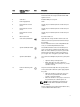
Indicator Description NOTE: The LED flashes once every two seconds. If the controller is not responding, it may indicate that the operating system did not load correctly. Solid green Indicates that the controller is clustered and fully functional. Fast blink green Indicates that the controller is in standby state and waiting to be clustered. NOTE: The LED flashes five times every second. Fast blink amber Indicates that the controller is currently in battery mode.
Power LED Indicator Codes Indicator Description Off Indicates that no power is available to the fan. Solid green Indicates that the power is on. Status LED Indicator Codes Indicator Description Off Indicates normal operating state. Blinking amber Indicates system fault or error condition. Cache Activity LED Indicator Codes The cache activity LED lights when the storage controller contains cache and when the cache is being transferred from the memory to the hard drive.
• For the full name of an abbreviation or acronym used in this document, see the Glossary at support.dell.com/ manuals. NOTE: Always check for updates on support.dell.com/manuals and read the updates first because they often supersede information in other documents.
Installing System Components 2 Recommended Tools You may need the following items to perform the procedures in this section: • • • • Key to the system keylock #2 Phillips screwdriver T8 and T15 Torx screwdrivers Wrist grounding strap connected to ground Front Bezel Installing The Front Bezel 1. Hook the right end of the bezel onto the chassis. 2. Fit the free end of the bezel onto the chassis. 3. Secure the bezel with the keylock. Figure 9. Removing and Installing the Front Bezel 1.
4. front bezel 5. locking hook Removing The Front Bezel 1. Unlock the keylock at the left end of the bezel. 2. Lift the release latch next to the keylock. 3. Rotate the left end of the bezel away from the front panel. 4. Unhook the right end of the bezel and pull the bezel away from the system. Controllers Your NAS appliance supports two redundant hot-swappable controllers. Removing A Controller CAUTION: Many repairs may only be done by a certified service technician.
Figure 10. Removing and Installing a Controller From the NAS Appliance 1. 2. 3. 4. controller slot in the NAS appliance controller controller handle release button Installing A Controller CAUTION: Many repairs may only be done by a certified service technician. You should only perform troubleshooting and simple repairs as authorized in your product documentation, or as directed by the online or telephone service and support team.
8. Log on to the NAS Manager and select Cluster Management → Hardware → Controllers Management. 9. Select the controller you want to attach. 10. Click Attach. Power Supplies Your system supports two hot-swappable 717 W AC power supply modules. When two identical power supplies are installed, the power supply configuration is redundant. In redundant mode, power is supplied to the system equally from both power supplies to maximize efficiency.
Figure 11. Removing and Installing an AC Power Supply 1. 2. 3. 4. 5. power supply release latch cable securing strap power supply handle power supply unit slot in NAS appliance chassis Installing A Power Supply CAUTION: Many repairs may only be done by a certified service technician. You should only perform troubleshooting and simple repairs as authorized in your product documentation, or as directed by the online or telephone service and support team.
NOTE: When installing or hot-swapping a new power supply, allow several seconds for the system to recognize the power supply and determine its status. The power-supply status indicator turns green to signify that the power supply is functioning properly. Cooling Fans Your system supports hot-swappable cooling fans.
Figure 12. Opening and Closing the Cooling Fan Access Door 1. cooling fan release latch 2. cooling fan access door 3. Press the fan release tabs (2) and pull the cooling fan out of the NAS appliance chassis.
Figure 13. Removing and Installing a Cooling Fan 1. fan release tabs (2) 2. cooling fans (6) 3. cooling-fan connectors (6) Installing A Cooling Fan CAUTION: Many repairs may only be done by a certified service technician. You should only perform troubleshooting and simple repairs as authorized in your product documentation, or as directed by the online or telephone service and support team. Damage due to servicing that is not authorized by Dell is not covered by your warranty.
WARNING: Opening or removing the NAS appliance cover when the system is on may expose you to a risk of electric shock. WARNING: This NAS appliance should only be opened by a certified Dell service technician as agreed to in your service contract. CAUTION: Many repairs may only be done by a certified service technician. You should only perform troubleshooting and simple repairs as authorized in your product documentation, or as directed by the online or telephone service and support team.
Figure 14. Opening and Closing the NAS Appliance 1. screws (4) 2. NAS appliance cover Closing The NAS Appliance NOTE: This is a service only procedure. 1. Offset the cover toward the front of the NAS appliance. 2. Align the notches on the edges of the chassis with the cover alignment pins on the inner sides of the cover. 3. Place the cover onto the chassis and offset the cover slightly to the front so that the cover lays flush with the chassis. 4.
Figure 15. Inside the NAS Appliance 1. 2. 3. 4. NAS appliance controllers (2) power supply units (2) power transmission boards (2) 5. information tag 6. cooling fans (6) 7. front LED status module Front LED Status Module Removing The Front LED Status Module WARNING: Whenever you need to lift the NAS appliance, get others to assist you. To avoid injury, do not attempt to lift the system by yourself. CAUTION: Many repairs may only be done by a certified service technician.
CAUTION: Label all the cables correctly before disconnecting any cables. Ensure that the cables are reconnected to the same ports when installing the controller. 4. Disconnect all the cables connected to the back of the NAS appliance. 5. Remove the controllers from the NAS appliance. 6. Remove the NAS appliance from the rack. 7. Open the NAS appliance. 8. Open the cooling fan access door and remove the cooling fan installed in fan bay 1.
Installing The Front LED Status Module WARNING: Whenever you need to lift the NAS appliance, get others to assist you. To avoid injury, do not attempt to lift the system by yourself. CAUTION: Many repairs may only be done by a certified service technician. You should only perform troubleshooting and simple repairs as authorized in your product documentation, or as directed by the online or telephone service and support team.
CAUTION: Label all the cables correctly before disconnecting any cables. Ensure that the cables are reconnected to the same ports when installing the controller. 4. Disconnect all the cables connected to the back of the NAS appliance. 5. Remove the controllers from the NAS appliance. 6. Remove the NAS appliance from the rack. 7. Open the NAS appliance. 8. Using a #2 Phillips screwdriver, loosen the two captive screws that secure the power transmission assembly to the chassis. 9.
Installing The Power Transmission Board Assembly WARNING: Whenever you need to lift the NAS appliance, get others to assist you. To avoid injury, do not attempt to lift the system by yourself. CAUTION: Many repairs may only be done by a certified service technician. You should only perform troubleshooting and simple repairs as authorized in your product documentation, or as directed by the online or telephone service and support team.
3. Disconnect all the cables connected to the back of the NAS appliance. 4. Remove the controllers from the NAS appliance. 5. Remove the NAS appliance from the rack. 6. Open the NAS appliance. 7. Remove the following: – power supply units – cooling fans – power transmission board assemblies 8. Disconnect the front LED status module cable from the midplane board. 9. Using a Torx 15 screwdriver, remove the 11 screws securing the midplane board to the NAS appliance chassis. 10.
The notches on the floor of the chassis hold the midplane board in place. 4. Using the Torx 15 screwdriver, replace the 11 screws to secure the midplane board on the chassis. 5. Connect the front LED status module cable to the midplane board. 6. Install the following: – power transmission board assemblies – cooling fans 7. – power supply units Install the NAS appliance in the rack. 8. Install the controllers in the NAS appliance.
Figure 19. Opening and Closing the Controller 1. release button 2. controller cover Closing The Controller CAUTION: Many repairs may only be done by a certified service technician. You should only perform troubleshooting and simple repairs as authorized in your product documentation, or as directed by the online or telephone service and support team. Damage due to servicing that is not authorized by Dell is not covered by your warranty. Read and follow the safety instructions that came with the product.
Figure 20. Inside the Controller 1. 2. 3. 4. controller backup power supply Internal USB port expansion-card riser cage 5. hard-drive assembly 6. memory modules (6) 7. processor heat sinks (2) Expansion Cards And Expansion-Card Risers NOTE: A missing or an unsupported expansion-card riser logs an SEL event. It does not prevent your system from powering on and no BIOS POST message or F1/F2 pause is displayed.
Figure 21. Removing and Installing the Expansion Card Riser 1. expansion-card riser cage 2. screws (2) 3. riser guide on controller chassis side wall (right) 4. expansion-card riser connectors on system board 5. 34 5. riser cage guide on controller chassis side wall (left) 6. riser cage guide pin Press the release latch on the expansion card holder, rotate and pull the expansion card holder away from the expansion card cage.
Figure 22. Removing and Installing the Expansion-Card Holder 1. 2. 3. 4. release latch card holder expansion-card cage notch 6. Using a #2 Philips screwdriver, loosen the captive screw that secures the expansion-card latch to the expansioncard riser cage. 7. Pull the expansion-card latch out of the expansion-card riser cage. 8. Hold the expansion card by its edges and remove it from the expansion-card connector on the riser.
Figure 23. Removing and Installing the Expansion Card 1. expansion card 2. expansion-card cage 3. expansion-card latch Installing The Expansion-Card Riser Cage And Expansion Cards CAUTION: Many repairs may only be done by a certified service technician. You should only perform troubleshooting and simple repairs as authorized in your product documentation, or as directed by the online or telephone service and support team.
8. Using the #2 Philips screwdriver, tighten the two captive screws that secure the expansion-card riser cage to the controller chassis. 9. Close the controller. 10. Install the controller in the NAS appliance.
Troubleshooting Your System 3 Safety First—For You And Your System CAUTION: Many repairs may only be done by a certified service technician. You should only perform troubleshooting and simple repairs as authorized in your product documentation, or as directed by the online or telephone service and support team. Damage due to servicing that is not authorized by Dell is not covered by your warranty. Read and follow the safety instructions that came with the product.
If the problem persists, see Getting Help.
Using System Diagnostics 4 If you experience a problem with your system, run the system diagnostics before contacting Dell for technical assistance. The purpose of running system diagnostics is to test your system hardware without risking data loss. If you are unable to fix the problem yourself, service and support personnel can use the diagnostics results to help you solve the problem. Dell Embedded System Diagnostics NOTE: Also known as Enhanced Pre-boot System Assessment (ePSA) diagnostics.
System Diagnostic Controls Menu Description Configuration Displays the configuration and status information of all detected devices. Results Displays the results of all tests that are executed. System Health Provides the current overview of the system performance. Event Log 42 Displays a time-stamped log of the results of all tests run on the system. This is displayed if at least one event description is recorded.
5 Technical Specifications NOTE: The following specifications apply to each controller.
Video Video type Integrated Matrox G200 Video memory 16 MB shared Environmental NOTE: For additional information about environmental measurements for specific system configurations, see dell.com/environmental_datasheets. Temperature Operating Continuous operation: 5 °C to 40 °C (41 °F to 104 °F) at 20% to 80% relative humidity (RH), with 26 °C maximum dew point. Derate maximum allowable dry bulb temperature at 1 °C/300 m above 900 m (1 °F per 550 ft).
Environmental Storage –305 m to 12192 m (–1000 ft to 40,000 ft) Airborne Contaminant Level Class G1 as defined by ISA-S71.
Getting Help 6 Contacting Dell NOTE: If you do not have an active Internet connection, you can find contact information on your purchase invoice, packing slip, bill, or Dell product catalog. Dell provides several online and telephone-based support and service options. Availability varies by country and product, and some services may not be available in your area. To contact Dell for sales, technical support, or customer service issues: 1. Visit support.dell.com. 2. Select your support category. 3.