
Manual

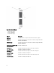

Item Indicator, Button, or
Connector
Icon Description
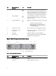
1 System identification button The identification buttons on the front and back panels
can be used to locate a particular system within a rack.
When one of these buttons is pressed, the system status
indicator on the back flashes until one of the buttons is
pressed again. Press to toggle the system ID on and off.
2 Power-on indicator The power LED lights green when at least one power
supply is connected to a power source and is supplying
power to the system.
3 System health indicator The system status LED lights only when the system power
is on.
• Lights blue during normal operation.
• Blinks amber when one of the controllers is
reporting hardware errors, battery errors, or if
one controller is missing.
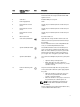
4 Cooling-fan access door Encloses and protects the hot-swappable cooling fans.
5 Cooling-fan access door
release latch
Press the access door release latch to expose the hot-
swappable cooling fans.
6 Service tag Displays the appliance service tag information.
7 Information tag A slide-out label panel listing the system NIC and BMC
MAC addresses for both controllers.
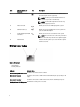
Back-Panel Features And Indicators
Figure 3. Back-Panel Features and Indicators
Item Indicator, Button, or
Connector
Icon Description
1 Power supply (PSU1) 717 W
2 Controller 1 Redundant NAS processing unit.
6