
Manual


Item Indicator, Button, or
Connector
Icon Description
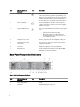
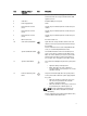
14 Service action button Used to troubleshoot certain errors. This button can be
pressed using the end of a paper clip.
NOTE: You must press and hold the button for ten
seconds to generate an SCI interrupt.
NOTE: Use this button only if directed to do so by
qualified support personnel.
15 Video connector Allows you to connect a VGA display to the system.
16 USB connectors (2) Allows you to connect USB devices to the system. The
ports are USB 2.0-compliant.
17 Serial COM port (mini USB
connector)
Allows you to connect a serial device to the system.
NOTE: This connector is for service only. Connect to
this connector only if asked to do so by Dell support.
18 PSU indicator Indicates whether power is present or whether a power
fault has occurred.
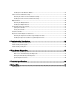
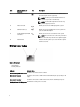
NIC Indicator Codes
Figure 4. NIC Indicator
1. link indicator
2. activity indicator
Indicator Indicator Code
Link and activity indicators are off The NIC is not connected to the network.
Link indicator is green The NIC is connected to a valid network at its maximum port speed (1 Gbps or 10
Gbps).
Link indicator is amber The NIC is connected to a valid network at less than its maximum port speed.
Activity indicator is blinking green Network data is being sent or received.
8