Dell Neworking S4810–Open Networking (ON) Installation Guide April 2014
Notes, Cautions, and Warnings NOTE: A NOTE indicates important information that helps you make better use of your computer. CAUTION: A CAUTION indicates either potential damage to hardware or loss of data and tells you how to avoid the problem. WARNING: A WARNING indicates a potential for property damage, personal injury, or death. Copyright © 2014 Dell Inc. All rights reserved. This product is protected by U.S. and international copyright and intellectual property laws.
Contents 1 About this Guide........................................................................................................ 5 Information Symbols............................................................................................................................. 5 Related Documents...............................................................................................................................6 2 The S4810–ON System...............................................................
Installing an AC Power Supply............................................................................................................24 Replacing an AC Power Supply.......................................................................................................... 25 6 Fans............................................................................................................................ 27 Components.........................................................................................
About this Guide 1 This guide provides site preparation recommendations, step-by-step procedures for rack mounting and desk mounting, inserting optional modules, and connecting to a power source. . CAUTION: To avoid electrostatic discharge (ESD) damage, wear grounding wrist straps when handling this equipment. WARNING: Only trained and qualified personnel can install this equipment. Read this guide before you install and power up this equipment. This equipment contains two power cords.
Related Documents For more information about the S4810–ON system, refer to the Dell Networking S4810–Open Networking (ON) Getting Started Guide. NOTE: For the most recent documentation, visit iSupport: http://www.dell.com/support/mysupport.
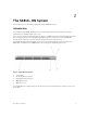
The S4810–ON System 2 The following sections describe the Dell Networking S4810–ON system. Introduction The Dell Networking S4810–ON platform is a next-generation switch/router designed to meet the requirements for distributed data center cores. It is a one-rack unit (RU) chassis that supports 48 ports of 10GbE small form-factor pluggable plus (SFP+) and four quad small form-factor pluggable plus (QSFP+) ports.
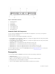
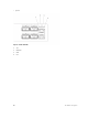
Figure 2. S4810–ON PSU-Side View 1. Mounting Bracket 2. Fan Module 1 3. Fan Module 2 4. Mounting Bracket 5. Power Supply (PSU2) 6. Power Supply (PSU1) 7. Grounding Screw Orderable S4810–ON Components You can order the S4810–ON system in several different configurations. You can also order optional modules and optics separately. You can order the following supported hardware components.
• Ground cable (not included, optional) • Ground cable screws (included) • Copper/fiber cables Other optional components are: • Additional power supply unit • Additional fan module • Additional mounting brackets (if installing in a four-post rack or cabinet) Features The S4810–ON offers the following features. • S4810–ON CPU and switch processor • Hot-swappable redundant power supply • 19 inch rack-mountable • Standard 1U chassis height Ports The S4810–ON offers the following ports.
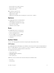
• System Figure 3. S4810–ON LEDs 1. SYS 2. MASTER 3. FAN 4.
Site Preparations 3 The S4810–ON is suitable for installation as part of a common bond network (CBN). You can install the system in: • network telecommunication facilities • data centers • other locations where the National Electric Code (NEC) applies For more information about S4810–ON specifications, refer to Specifications. NOTE: Install the S4810–ON system into a rack or cabinet before installing any optional components.
Rack Mounting When you prepare your equipment rack, ensure that the rack is earth ground. Ground the equipment rack to the same ground point the power service in your area uses. The ground path must be permanent. Grounding (Optional) Use the S4810–ON in a common bond network (CBN). Connect the grounding cables as described in Install the S4810-ON. Fans and Airflow The S4810–ON fans support two airflow options. Be sure to order the fans suitable to support your site’s ventilation.
Storing Components If you do not install your S4810–ON and components immediately, Dell Networking recommends properly storing the system and all optional components until you are ready to install them. WARNING: ESD damage can occur when components are mishandled. Always wear an ESDpreventive wrist or heel ground strap when handling the S4810–ON and its accessories. After you remove the original packaging, place the S4810–ON and its components on an antistatic surface.
Install the S4810–ON 4 To install the S4810–ON system, Dell Networking recommends completing the installation procedures in the order presented in this chapter. Always handle the S4810–ON and its components with care. Avoid dropping the system or its field replaceable units (FRUs). This chapter describes the installation procedures as follows: 1. Installing the S4810–ON Chassis in a Rack or Cabinet a. Attaching the Mounting Brackets into a Two-Post Rack or Cabinet b.
To attach the brackets to the system, follow these steps. 1. Take the brackets and screws out of their packaging. 2. Attach the brackets to the PSU sides of the system using four screws for each bracket. Attach the bracket so that the “ear” is parallel to the PSU and the outside of the system. Figure 4. Attaching Mounting Brackets into a Two-Post Rack or Cabinet 1. 3. 5. View from the chassis I/O side Screws Connect to the Rack or Cabinet (ears) 2. 4. 6.
NOTE: Dell Networking recommends using one person to hold the S4810–ON chassis in place while another person attaches the brackets to the posts. Attach the bracket “ears” to the rack or cabinet posts using the two screws for each bracket. Ensure the screws are tightened firmly. Figure 5. Installing the System into a Two-Post Rack or Cabinet 1. 3. PSU1 Rack Mounting Ears 2. 4.
3. Attach the brackets to the PSU sides of the chassis using four screws for each bracket. Attach the bracket so that the “ear” is parallel to the PSU and the outside of the chassis. Figure 6. Attaching the Mounting Brackets into a Four-Post Rack or Cabinet 1. 3. 5. View from the chassis I/O side Screws Connect to the rack or cabinet (ears) 2. 4. 6. Connect to the rack or cabinet Screws Power Supply 4. Attach the long bracket to each side of the chassis using the provided countersink screws.
3. Fasten the system to the PSU-facing posts using rack mount screws (not included with the system). Figure 7. Installing the System into a Four-Post Rack or Cabinet 1. 3. 5. 4. I/O Side Long Brackets PSU Side 2. 4. Rack Ears Rack Ears Use the provided pan head screws to attach the rack ears on the I/O-facing posts to the long bracket previously attached to the system. Tighten the pan head screws to secure the system.
3. Attach the one-hole lug to the chassis using the supplied 10-32 screw with the captive internal tooth lock washer. Torque the screw to 20 in-lbs. Figure 8. Attaching the Ground Cable a. 4. Lug hole b. Ground Screw Attach the other end of the ground cable to a suitable ground point. The rack installation ears are not a suitable grounding point. Installing the SFP+ and QSFP+ Optics The S4810–ON has 48 SFP+ optical ports and four QSFP+ optical ports.
Remove the SFP+ and QSFP+ Optics Remove an optic by pushing the tab on the optic and sliding the optic from the port. When removing optics with direct attach cables (DACs) from the port, pull the release tab firmly and steadily. Prior to pulling the release tab, you may need to gently push the optic into the port to ensure it is seated properly. Do not jerk or tug repeatedly on the tab.
Figure 9. AC Power Connection 1. Power Connection 2. LED After Installing the S4810–ON After you have securely installed and powered on the S4810-ON, refer to your ONIE-compatible thirdparty operating system documentation to configure your system.
Power Supplies 5 The S4810–ON supports two hot-swappable power supply units (PSUs) with integrated fans that provide cooling for the system. The S4810–ON supports AC power supplies with two air-flow directions (normal and reversed). Two PSUs are required for full redundancy, but the system can operate with a single PSU. NOTE: If you use a single PSU, install a blank plate in the other PSU slot. Dell Networking recommends using power supply 2 (PSU2) as the blank plate slot. The PSUs are field replaceable.
Installing an AC Power Supply To install an AC power supply, follow these steps. NOTE: The PSU slides into the slot smoothly. Do not force a PSU into a slot as this action may damage the PSU or the S4810–ON chassis. NOTE: Ensure that the PSU is correctly installed. When the PSU is correctly installed, the power connector is on the left side of the PSU and the status LED is at the top of the PSU (refer to the following illustration). Figure 10. Installing an AC Power Supply 1. PSU1 2. Fan Module 3.
Replacing an AC Power Supply To replace an AC power supply, follow these steps: NOTE: The PSU slides into the slot smoothly. Do not force a PSU into a slot as this action may damage the PSU or the S4810–ON chassis. NOTE: If a PSU fails, you must completely replace it. There are no field serviceable components in the PSU. To request a hardware replacement, refer to Technical Support. NOTE: If you use a single PSU, you must install a blank plate in the other PSU slot.
Fans 6 The S4810–ON comes from the factory with one power supply unit (PSU) and two fan modules installed in the system. If two or more fans are installed and running, the fan modules are hot-swappable. NOTE: To run the system, both slots must have operating fan units. If a module is not installed in each slot (either as part of the PSU or as an independent fan module), the system shuts down in one minute.
Figure 11. S4810–ON Fan Module 1. PSU1 2. Fan Module 1 3. Fan Module 2 4. Grab Handle 5. PSU2 Installing a Fan Module The fan modules in the S4810–ON are field replaceable. Module slot 0 is on the left side of the chassis; module slot 1 is on the right side of the chassis. CAUTION: DO NOT mix airflow directions. Both fans must use the same airflow direction (reverse or normal). To install a fan module, follow these steps. 1. Take the fan module out of the shipping box. 2.
4. Fans Tighten the captive screws on the replacement module with a screwdriver. Ensure that the module is secure.
Console Ports 7 You can access the S4810–ON directly through the console port at the input/output (I/O) side of the system. Accessing the RJ-45 Console Port (RS-232) The RS-232/RJ-45 console port is labeled on the upper-right-hand side of the S8410–ON chassis (the I/O side) (as shown in the following illustration). NOTE: Before starting this procedure, be sure that you have a terminal emulation program already installed on your PC. Figure 12. S4810–ON Serial Console Port Connector 1.
Access the RJ-45 Console Port with a DB-9 Adapter If the DTE has a DB-9 interface, you can connect to the console using an RJ-45 to DB-9 adapter along with the RJ-45 rollover cable. The following table lists the pin assignments. Table 1.
8 Specifications This chapter lists the S4810–ON specifications. Chassis Physical Design Table 2. Chassis Physical Design Parameter Specifications Height 1.73 inches (4.4 cm) Width 17.32 inches (44.0 cm) Depth 18.11 inches (46 cm) Chassis weight with factory-installed components 14.39 pounds (approx.) (6.54 kg) Rack clearance required Front: 5-inches (12.7 cm) Rear: 5-inches (12.7 cm) Thermal dissipation 1194 BTH/h Power consumption 250 Watts (nominal) 350 Watts (maximum) Table 3.
IEEE Standards The S4810–ON complies with the following IEEE standards. • • • • • 802.3ab Gigabit Ethernet (1000BASE-T) 802.3ae 10 Gigabit Ethernet (10GBASE-X) 802.3ba 40 Gigabit Ethernet (40GBase-SR4, 40GBase-CR4) on optical ports 802.3u Fast Ethernet (100BASE-TX) 802.3z Gigabit Ethernet (1000BASE-X) Agency Compliance The S4810–ON is designed to comply with the following safety and agency requirements.
derived for commercial and industrial environments to provide reasonable protection against interference with licensed communication equipment. WARNING: This is a Class A product. In a domestic environment, this device may cause radio interference, in which case, you may be required to take adequate measures. European Community Contact Dell Networking, EMEA - Central Dahlienweg 19 66265 Heusweiler Germany http://www.force10networks.
Korean Package Label Safety Standards and Compliance Agency Certifications • CUS UL 60950-1, 2nd Edition • CSA 60950-1-03, 2nd Edition • EN 60950-1, 2nd Edition • EN 60825-1, 1st Edition • EN 60825-1 Safety of Laser Products—Part 1: Equipment Classification Requirements and User’s Guide • EN 60825-2 Safety of Laser Products—Part 2: Safety of Optical Fibre Communication Systems • FDA Regulation 21CFR 1040.10 and 1040.
Waste Electrical and Electronic Equipment (WEEE) Directive for Recovery, Recycle and Reuse of IT and Telecommunications Products Dell Networking switches are labeled in accordance with European Directive 2002/96/EC concerning waste electrical and electronic equipment (WEEE). The Directive determines the framework for the return and recycling of used appliances as applicable throughout the European Union.
4. Remove the card. Figure 15. Illustration of removing the SD Card Replacing the Battery on the S4810–ON The lithium battery is not field replaceable. Only authorized personal should remove and replace the battery. If the battery requires replacement, contact Dell Networking Technical Support. WARNING: ESD damage can occur if components are mishandled. Always wear an ESDpreventive wrist or heel ground strap when handling the S4810–ON and its components.
To open the case, follow these steps. 1. Remove the small Phillips screws that connect the top of the case to the body. There are three screws evenly spaced across the rear and three screws evenly spaced along each side of the case. 2. Slide the top backwards until its front flange slides free of the faceplate then lift it off. Figure 16.
Figure 17. Close-Up View of the Battery Batteries or packaging for batteries are labeled in accordance with European Directive 2006/66/EC concerning batteries and accumulators and waste batteries and accumulators. The Directive determines the framework for the return and recycling of used batteries and accumulators as applicable throughout the European Union.
Figure 18. The European WEEE Symbol For California: • Perchlorate Material — Special handling may apply. • Refer to http://www.dtsc.ca.gov/hazardouswaste/perchlorate The foregoing notice is provided in accordance with California Code of Regulations Title 22, Division 4.5 Chapter 33. Best Management Practices for Perchlorate Materials.
Technical Support 9 This chapter contains the following sections: • The iSupport Website • Contacting the Technical Assistance Center • Requesting a Hardware Replacement The iSupport Website iSupport provides a range of documents and tools to assist you with effectively using Dell Networking equipment and mitigating the impact of network outages.
Managing Your Case Log in to iSupport and select the Service Request tab to view all open cases and Return Materials Authorizations (RMAs). Technical Documentation Log in to iSupport and select the Documents tab. You can access this page without logging in using the Documentation link on the iSupport page. Contact Information E-mail: Dell-Force10_Technical_Support@Dell.com Web: http://www.dell.com/support Telephone: • US and Canada: 1.866.965.5800 • International: +1.408.965.