Dell Storage MD1400 Enclosures Hardware Owner's Manual
Notes, cautions, and warnings NOTE: A NOTE indicates important information that helps you make better use of your computer. CAUTION: A CAUTION indicates either potential damage to hardware or loss of data and tells you how to avoid the problem. WARNING: A WARNING indicates a potential for property damage, personal injury, or death. © 2014 - 2019 Dell Inc. or its subsidiaries. All rights reserved. Dell, EMC, and other trademarks are trademarks of Dell Inc. or its subsidiaries.
Contents 1 About your enclosure.................................................................................................................... 5 Physical specifications.......................................................................................................................................................... 5 Front-panel features and indicators....................................................................................................................................
3 Troubleshooting your enclosure................................................................................................... 28 Safety first—for you and your enclosure.........................................................................................................................28 Troubleshooting enclosure startup failure........................................................................................................................28 Troubleshooting loss of communication.............
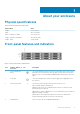
1 About your enclosure Physical specifications Table 1. Enclosure dimensions and weight Measurement Value Height 8.7 cm (3.43 in) Width 48.2 cm (18.98 in) Depth - includes PSU handle 59.2 cm (23.3 in) Weight - maximum configuration 28.39 kg (62.58 lb) Weight - empty 9.0 kg (19.8 lb) Front-panel features and indicators Figure 1.
Front-bezel features and indicators Figure 2. Front-bezel features and indicators Item Indicator, Button, or Connector 1 Enclosure status LED Icon Description Figure 3. The enclosure status LED lights when the enclosure power is on. Lights solid blue during normal operation. Blinks blue when a host server is identifying the enclosure or when the system identification button is pressed. Blinks amber or remains solid amber for a few seconds and then turns off when the EMMs are booting or resetting.
Hard disk drive indicator patterns Figure 4. Hard disk drive indicators 1. hard disk drive activity indicator (green) 2. hard disk drive status indicator (green and amber) 3.
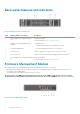
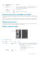
Back-panel features and indicators Figure 5. Back-panel features and indicators Item Indicator, Button, or Connector Description 1 Power supply unit or cooling fan module (PS1) 600 W power supply. Primary enclosure management module (EMM 0) The EMM provides: • a data path between the enclosure and the host server. 3 Secondary EMM (EMM 1) • enclosure management functions for your enclosure. 4 Information tag A slide-out label panel, which allows you to record Service Tag.
Item Indicator, Button, or Connector Icon Description 1,2,3,4 SAS port (Input or Output) Provides SAS connections for cabling the host or an upchain expansion enclosure and to the next down chain expansion enclosure in a daisy chain.(Single Port, Redundant, and Multi-chain Configuration) 5 USB Mini-B (serial debug port) For engineering use only. 6 7-Segment Display Display the enclosure location in SAS Chain.
Item 3 LED Icon AC power Color Green State • • OFF — OK. Blinks briefly when power is first turned on to the power supply module. • ON — Power supply module is connected to a source of AC power irrespective of whether or not a power switch is on. OFF — Power supply module is completely disconnected from any source of AC power. • Other information you may need WARNING: See the safety and regulatory information that shipped with your system.
2 Installing enclosure components Recommended tools You may need the following items to perform the procedures in this section: • • • Key to the system keylock #2 Phillips screwdriver Wrist grounding strap Front bezel (optional) Removing the front bezel 1. 2. 3. 4. Using the system key, unlock the front bezel (if locked). Lift the release latch next to the keylock. Pull the left end of the bezel away from the front panel. Unhook the right end of the bezel and pull the bezel away from the system.
Hard disk drives Safety: Models AMT, E03J, and E04J Models AMT, E03J, and E04J are intended for installation only in restricted access locations as defined in cl 1.2.7.3 of IEC 60950-1:2005. On the basis of your configuration, your enclosure either supports up to up to 12 3.5-inch SAS hard disk drives in internal drive bays. Hard disk drives are connected to a backplane using hard disk drive carriers and are configured as hot-swappable.
support team. Damage due to servicing that is not authorized by Dell is not covered by your warranty. Read and follow the safety instructions that came with the product. 1. If installed, remove the front bezel. See Removing the front bezel. 2. From the management software, prepare the hard disk drive for removal. Wait until the hard disk drive indicators on the hard disk drive carrier indicates that the drive can be removed safely.
Removing a hard disk drive from a hard disk drive carrier 1. Remove the four screws from the slide rails on the hard disk drive carrier. 2. Lift the hard disk drive out of the hard disk drive carrier. Remove the screws from the slide rails on the hard disk drive carrier and separate the hard disk drive from the carrier. Figure 11. Removing and installing a hard drive into a 3.5-inch hard disk drive carrier 1. screws (4) 2. hard disk drive 3.
Figure 12. Removing and installing an EMM blank 1. EMM blank 2. release latch Installing an EMM blank To install an EMM blank, align the blank with the EMM bay and insert the blank into the chassis until it clicks into place. Removing an EMM CAUTION: Many repairs may only be done by a certified service technician. You should only perform troubleshooting and simple repairs as authorized in your product documentation, or as directed by the online or telephone service and support team.
Figure 13. Removing and installing an EMM 1. release lever 2. EMM 3. release tab Installing an EMM CAUTION: Many repairs may only be done by a certified service technician. You should only perform troubleshooting and simple repairs as authorized in your product documentation, or as directed by the online or telephone service and support team. Damage due to servicing that is not authorized by Dell is not covered by your warranty. Read and follow the safety instructions that came with the product. 1. 2. 3.
Removing an AC power supply unit or cooling fan module NOTE: If you remove a fully functioning power supply or cooling fan module, the fan speed in the remaining module increases significantly to provide adequate cooling. The fan speed decreases gradually when a new power supply or cooling fan module is installed. 1. Turn off the power supply unit or cooling fan module. 2. Disconnect the power cable from the power source. 3.
Figure 15. Securing the power cable a. Velcro strap CAUTION: When connecting the power cable, secure the cable with the Velcro strap. NOTE: If the enclosure is powered on, all the power supply LEDs remain off until the AC power cable is connected to the power supply unit or cooling fan module and the power switch is turned on. 4. Turn on the power supply unit or cooling fan module. About DC power supply units An MD Series storage array receives its power from two power supply modules.
Item LED Color State 1 Power output Green • • ON — Normal operation. Power supply is connected to DC power and the power switch is on. The power supply module is supplying DC power to the array. OFF — Indicates any one of the following: • • • The power switch is off. The power supply module is not connected to power. There is a fault condition. 2 Power supply module fault Yellow • • • ON — Fault detected. OFF — OK. Blinks briefly when power is first turned on to the power supply module.
• Molex # 39422-0012 mating DC power connector Required Tools • • Hand-crimping tool (Tyco Electronics, 58433-3 or equivalent). Wire-stripper pliers capable of removing insulation from size 10 AWG solid or stranded, insulated copper wire. NOTE: Use alpha wire part number 3080 or equivalent (65/30 stranding).
must comply with applicable local or national codes and practices. Damage due to servicing that is not authorized by Dell is not covered by your warranty. Read and follow all safety instructions that came with the product. The DC power supply module must be hard-wired to a DC power source in your environment by a qualified electrician. To wire your DC power supply module to a DC power source: 1. Make sure that the power switch is in the OFF position, and the power supply module is turned off. 2.
Figure 20. Connecting the dc power cables a. attached (trapped) finger screws b. connector on the power supply cable c. connector on the power supply module Removing a DC power supply WARNING: For equipment using –(48–60) V DC power supplies, a qualified electrician must perform all connections to DC power and to safety grounds. Do not attempt connecting to DC power or installing grounds yourself .All electrical wiring must comply with applicable local or national codes and practices.
Figure 21. Removing and installing a dc power supply module a. release latch b. power supply module c. power supply module handle Installing a DC Power Supply Module NOTE: For equipment using –(48–60) V DC power supplies, a qualified electrician must perform all connections to DC power and to safety grounds. Do not attempt connecting to DC power or installing grounds yourself. All electrical wiring must comply with applicable local or national codes and practices.
NOTE: When viewing the rear of the array, power supply module 0 is on the left, and power supply module 1 is on the right. Troubleshooting a DC power supply WARNING: For equipment using –(48–60) V DC power supplies, a qualified electrician must perform all connections to DC power and to safety grounds. Do not attempt connecting to DC power or installing grounds yourself. All electrical wiring must comply with applicable local or national codes and practices.
Temperature Maximum operation ambient temperature 35° C For information about supported expanded operating temperature range and configurations, see dell.com/support/manuals. Control panel Removing the control panel 1. Turn off the enclosure and host server. 2. Disconnect all the power cables connected to the enclosure. 3. Remove the hard disk drives from slot 0 to 2. See Removing a hard disk drive. 4.
CAUTION: Many repairs may only be done by a certified service technician. You should only perform troubleshooting and simple repairs as authorized in your product documentation, or as directed by the online or telephone service and support team. Damage due to servicing that is not authorized by Dell is not covered by your warranty. Read and follow the safety instructions that came with the product. Removing the backplane 1. Turn off the enclosure and disconnect it from the electrical outlet. 2.
Figure 24. Removing and installing the backplane a. screws (5) b. captive screws (2) c. backplane Installing the backplane 1. Align the holes on the backplane with the holes on the enclosure. 2. Tighten the captive screw to secure the backplane to the chassis. 3. Replace the screws that secure the backplane to the chassis. 4. Align the slots on the EMM or power supply cage with the tabs on the chassis. 5. Push the EMM or power supply cage toward the front of the enclosure. 6.
3 Troubleshooting your enclosure Safety first—for you and your enclosure CAUTION: Many repairs may only be done by a certified service technician. You should only perform troubleshooting and simple repairs as authorized in your product documentation, or as directed by the online or telephone service and support team. Damage due to servicing that is not authorized by Dell is not covered by your warranty. Read and follow the safety instructions that came with the product.
module can be removed from a powered-on enclosure for a maximum period of five minutes. Beyond that time, the enclosure may automatically shut down to prevent damage. 2. Reseat the power supply by removing and reinstalling it. See AC power supply unit or cooling fan module. NOTE: After installing a PSUs, allow several seconds for the enclosure to recognize the PSUs and to determine if it is working properly. If the problem is not resolved, see Getting Help. 3.
support team. Damage due to servicing that is not authorized by Dell is not covered by your warranty. Read and follow the safety instructions that came with the product. 1. Remove the hard disk drive from the enclosure. See Removing a hard disk drive. NOTE: You must ensure that you check the hard disk drive indicators before removing the faulty hard disk drive from the enclosure. 2. Check the hard disk drives and the backplane to ensure that the connectors are not damaged. 3. Reinstall the hard disk drive.
1. Ensure that the following components are properly installed: • • • • • Hard disk drives EMMs Power supply unit or cooling fan modules Control panel Backplane 2. Ensure that all the cables are properly connected and that there are no damaged pins in the connectors. 3. Run diagnostics available in Server Administrator. If the test fails, see Getting Help.
4 Getting help Topics: • • Contacting Dell Documentation feedback Contacting Dell Dell provides several online and telephone-based support and service options. If you do not have an active internet connection, you can find contact information on your purchase invoice, packing slip, bill, or Dell product catalog. Availability varies by country and product, and some services may not be available in your area. To contact Dell for sales, technical assistance, or customer-service issues: 1. Go to Dell.