SC460 Expansion Enclosure Owner's Manual Regulatory Model: CYAE
Notes, Cautions, and Warnings NOTE: A NOTE indicates important information that helps you make better use of your product. CAUTION: A CAUTION indicates either potential damage to hardware or loss of data and tells you how to avoid the problem. WARNING: A WARNING indicates a potential for property damage, personal injury, or death. © 2017 – 2018 Dell Inc. or its subsidiaries. All rights reserved. Dell, EMC, and other trademarks are trademarks of Dell Inc. or its subsidiaries.
Contents About this Guide...............................................................................................................................................5 Revision History..................................................................................................................................................................5 Audience..........................................................................................................................................................
Remove a Hard Drive................................................................................................................................................ 35 Install a Hard Drive..................................................................................................................................................... 37 Cooling Fan Modules.......................................................................................................................................................
Preface About this Guide This guide describes how to perform service and maintenance on the SC460 expansion enclosure.
Provides instructions for getting started with Windows PowerShell cmdlets and scripting objects that interact with the Storage Center using the PowerShell interactive shell, scripts, and PowerShell hosting applications. Help for individual cmdlets is available online. • Storage Manager Administrator’s Guide Provides instructions for using the Storage Manager software. • Dell TechCenter Provides technical white papers, best practice guides, and frequently asked questions about Dell Storage products.
1 About the SC460 Expansion Enclosure An SC460 expansion enclosure provides expansion storage for a Storage Center. The SC460 expansion enclosure connects directly to the SAS ports on the back of the storage system.
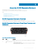
SC460 Expansion Enclosure Back Panel Features and Indicators The SC460 back panel provides controls to power up and reset the expansion enclosure, indicators to show the expansion enclosure status, and connections for back-end cabling. Figure 2. SC460 Back Panel Features and Indicators Item Name Description 1 Power supply unit and cooling fan module (PS1) Contains redundant 900 W power supplies and fans that provide cooling for the expansion enclosure.
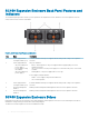
Figure 3. SC460 Drive Indicators Item Name 1 Drive activity indicator 2 Drive status indicator Description • • Blinking blue – Drive activity Steady blue – Drive is detected and has no faults • • • Off – Normal operation Blinking amber (on 1 sec. / off 1 sec.
Figure 4.
2 SC460 Expansion Enclosure Installation This chapter describes how to install an SC460 expansion enclosure. Safety Precautions Always follow these safety precautions to avoid injury and damage to Storage Center equipment. If equipment described in this guide is used in a manner not specified by Dell, the protection provided by the equipment could be impaired. For your safety and protection, observe the rules described in the following sections.
• Provide a suitable power source with electrical overload protection. All Storage Center components must be grounded before applying power. Make sure that a safe electrical earth connection can be made to power supply cords. Check the grounding before applying power. • The plugs on the power supply cords are used as the main disconnect device. Make sure that the socket outlets are located near the equipment and are easily accessible.
Unpacking Storage Center Equipment Unpack the expansion enclosure and identify the items in your shipment. Figure 5. Expansion Enclosure Components 1 Expansion enclosure 2 Rack rails (2) 3 Mini-SAS HD cables (2) 4 Power cables (4) 5 Front bezel (Optional) 6 Documentation Determine the Mounting Location Determine where to mount the SC460 expansion enclosure in the rack. 1 Identify a location in the rack with 4U of space for the expansion enclosure.
Figure 6. Mounting Location from Front and Back of Rack 1 Location for the clip nuts to secure the top cover 2 Location for the clip nuts to secure the expansion enclosure 3 Location for the expansion enclosure rack rails 4 Location for the 1U cable management tray rails Install the Cable Management Tray If you plan to use the 1U cable management tray, install the tray before installing the SC460 expansion enclosure.
About this task Install the 1U cable management tray into a rack with a depth of 1070 mm (42.1 in.). Steps 1 The 1U cable management tray rails are shipped with alignment pins that are designed to fit into a standard rack. To install the rails in a non-standard rack, remove the alignment pins from the rails and install the appropriate square hole or threaded hole alignment pins. a b c Using a flat-head screwdriver, remove the alignment pins from the front and back of the rails.
7 Prepare the cable chains and route the cables through the cable chains. NOTE: Label the cables before routing them through the cable chains. a b Align the cable chains so the latches are facing up and the hinges are all facing each other. Unclip and open the all of the latches on the cable chains. Figure 9. Open the Cable Chain Latches c d e f Route two power cables and two Mini-SAS HD cables through each cable chain. Close the latches and make sure that they are snapped shut.
Figure 11. Attach Cable Chains to Tray Rails 9 Install the chassis bracket into the brackets on the side of the chassis. Figure 12. Install the Chassis Bracket to the Chassis 10 Attach the clips on free end of the cable chains to the center flange on the chassis bracket.
Figure 13. Clip Cable Chains to Chassis Bracket 11 Place the bezel over the front of the tray by pressing the release buttons on the bezel and placing it over the retaining slots on the tray. Figure 14. Install the Front Bezel Modify the Rail Lengths Use this procedure to extended or shorten the lengths of the expansion enclosure rails. About this task The rails have four adjustment ranges: 18-22", 22-26", 26-30", 30-34". The default length of the rails is 22-26".
The length adjustment bracket will be free of the rail. Figure 15. Remove Screws and Nuts 4 Move to the front of the rail and align the mounting slots with the mounting holes. 5 Slide the inner rail mechanism until the 18"-22", 26"-30", or 30"-34" mark is visible. If the inner mechanism is locked, depress the leaf spring and press the rail locking mechanism to free it. 6 Adjust the hardware to make sure that the mounting holes are aligned with the mounting slots.
c Push the rail back to secure the rail to the rack post. An audible click indicates that the rail is secure in the post. Figure 16. Attach Rail to the Back of the Rack 3 Attach the right rail to the front post of the rack. a b Align the right rail with the lower two U spaces of the 4U mounting location. Pull the rail forward, with the alignment pins in the middle holes of the bottom two U spaces of the 4U mounting location. An audible click indicates that the rail is secure in the post. Figure 17.
Figure 18. Extend the Rails from the Rack d e f Slide the extended rails over the expansion enclosure chassis rails. Remove the four handles from the sides of the expansion enclosure chassis. Slide the expansion enclosure chassis into the rack. Figure 19. Mount the Expansion Enclosure into the Rack 6 If the drives, fans, PSUs, and EMMs were removed from the expansion enclosure chassis, reinstall these components in the chassis. 7 Secure the expansion enclosure chassis and top cover.
c d e Make sure that the self-locking latches are pushed in and fully engaged to prevent the expansion enclosure chassis from sliding out of the rack. Secure the expansion enclosure chassis to the rack using the orange shoulder screws. If the top cover is secured by two small shipping screws, remove the screws. Secure the top cover of the expansion enclosure chassis to the rack using the shoulder screws.
Figure 21. Installing Cable Management Arms 4 Swing the extension arm into alignment with the rail bracket. Figure 22. Align Extension Arm with Rail Bracket 5 Push the extension arm into the rail bracket until you hear an audible click. The audible click indicates that the cable management arm is secure.
Figure 23. Insert Extension Arm into Rail Bracket 6 Repeat the previous steps for the second cable management arm. 7 Route the cables though the cable management arms. NOTE: Label all the cables before routing them through the cable management arms. a b c 8 Open the plastic brackets on the cable management arm. Route the power cables and the Mini-SAS HD cables through the plastic brackets. Close the plastic brackets on the cable management arm. Close the cable management arms.
Figure 24. Swing Lower Arm to Left Side of Chassis b c d Swing the upper arm back and to the right side of the chassis. Align the securing tab on the right end of the lower arm with the notch over the orange release tab. Press the tab into the slot until you hear a click. The click indicates that the arm is secure. Figure 25.
Figure 26. Secure Cable Management Arm 9 Verify that the cable management arms are attached at the securing tabs. Figure 27. Verify that Cable Management Arms are Secure 10 Connect the power cables and the Mini-SAS HD cables to the expansion enclosure. Next steps 1 Power on the expansion enclosure and storage system. 2 Use SupportAssist to send diagnostic data to technical support.
Installing the Expansion Enclosure in a Non-Standard Rack Follow these best practice guidelines when installing the SC460 expansion enclosure in a non-standard rack: • A non-standard rack might have PDUs that face into the rack. This might cause interference between the expansion enclosure and/or rear cable management arms (if used). Carefully plan and route cables to minimize any interference. It might be necessary to use a different type of PDU that is mounted in the main rack area.
Part Part Number Description Steps 1 Determine where to mount the SC460 expansion enclosure in the rack. 2 If necessary, use the screwdriver to adjust the length of the expansion enclosure rack rails to fit the rack. 3 The rails are shipped with 6.8 mm alignment pins that are designed to fit into a standard rack. To install the rails in a non-standard rack, you might need to replace the alignment pins in the rails with the appropriate alignment pins.
Part Part Number Description Used to secure the expansion enclosure chassis and top cover to a rack with #10-32 threaded holes 036-032-012 #12-24 x 1/2 in. truss head Phillips screw with nylon patch (Quantity: 6) Used to secure the expansion enclosure chassis and top cover to a rack with #12-24 threaded holes Steps 1 Remove the semi-captive M5 shoulder screws from the expansion enclosure chassis and top cover.
Install the Front Bezel If a front bezel is shipped with the SC460 expansion enclosure, install the bezel on the front of the expansion enclosure. 1 Align the bezel with the front of the expansion enclosure. 2 Press the two latches on front of bezel. Figure 29. Install the Bezel 3 Push the bezel into place until it attaches to the expansion enclosure. 4 Release the latches on the front on the bezel. 5 If the bezel has key lock, lock the bezel with the key.
3 Replacing SC460 Expansion Enclosure Components This chapter describes how to replace field replaceable units (FRUs) inside the SC460 expansion enclosure. This chapter assumes that the installer has received the FRU and is ready to install it in the expansion enclosure.
You must use a mechanical lift to install the expansion enclosure chassis if you do not remove the drives, cooling fans, PSUs, and EMMs from the chassis. • Dell recommends that only individuals with rack-mounting experience install an SC460 expansion enclosure in a rack. • When installing multiple expansion enclosures in a rack, fill the rack from the bottom up and empty the rack from the top down. • The rack construction must support the total weight of the installed expansion enclosures.
Figure 31. Install the Bezel 3 Push the bezel into place until it attaches to the expansion enclosure. 4 Release the latches on the front on the bezel. 5 If the bezel has key lock, lock the bezel with the key. Pre-Replacement Procedures Perform the procedures described in this chapter before replacing a component of the SC460 expansion enclosure. Send Diagnostic Data Using SupportAssist Before replacing components, use SupportAssist to send diagnostic data to technical support.
Shut Down the Storage System and Expansion Enclosures If the replacement component is not hot-swappable, use the Storage Manager to shut down the storage system and expansion enclosures. Shutting down the storage system and expansion enclosures results in a system outage, so plan to perform these procedures during a maintenance window. Prerequisites Before shutting down the storage system and expansion enclosures, perform the following tasks: 1 Identify the part to replace. 2 Locate the replacement part.
The location of the failed hard drive is displayed in the Disk View tab. Figure 33. Disk View Showing the Failed Hard Drive Remove a Hard Drive Use this procedure to remove a hard drive from the expansion enclosure. Prerequisites 1 Use SupportAssist to send diagnostic data to technical support. 2 Change the operation mode of the Storage Center to Maintenance. About this task You can remove a hard drive without shutting down the expansion enclosure.
Figure 34. Releasing a Hard Drive • If the drive fault LED is on, pull the drive up an additional 5 cm (2 in.). Wait 30 seconds for the drive to stop spinning and pull the drive completely out of the slot. • If the drive fault LED is off, pull the drive completely out of the slot. Figure 35.
Install a Hard Drive Use this procedure to install a hard drive in the expansion enclosure. About this task Do not drop the hard drive into the slot. Dropping the hard drive into the slot might damage the drive and the drive interface backplane, which requires a full chassis replacement to repair. CAUTION: A drive must be replaced within 10 minutes of extending the expansion enclosure from the rack. Steps 1 Open the latch on the drive carrier.
Cooling Fan Modules The SC460 expansion enclosure supports three cooling fan modules. If one cooling fan module fails, the remaining cooling fan modules continue to cool the expansion enclosure. NOTE: When a cooling fan module fails, the fan speed in the remaining modules increases significantly to provide adequate cooling. The cooling fan speed decreases gradually when a new cooling fan module is installed.
Figure 38. Rear View of the Expansion Enclosure Showing the Failed Cooling Fan Module Remove a Cooling Fan Module Use this procedure to remove a cooling fan module. Prerequisites 1 Use SupportAssist to send diagnostic data to technical support. 2 Change the operation mode of the Storage Center to Maintenance. About this task You can remove a cooling fan module without shutting down the expansion enclosure.
Figure 39. Removing a Cooling Fan Module Install a Cooling Fan Module Use this procedure to install a cooling fan module. About this task The expansion enclosure must have at least two cooling fan modules installed while the expansion enclosure is powered up. Do not remove more than one cooling fan module while AC power is on. CAUTION: A cooling fan module must be replaced within five minutes of extending the expansion enclosure from the rack.
Figure 40. Installing a Cooling Fan Module 5 Wait for the expansion enclosure to recognize the cooling fan module and determine its status. 6 Push the expansion enclosure chassis back into the rack. 7 In Storage Manager, make sure that the cooling fan module is recognized and shown as up and running. Next steps 1 Use SupportAssist to send diagnostic data to technical support. 2 Change the operation mode of the Storage Center to Normal.
Figure 41. Hardware Alert Identifying the Expansion Enclosure with the Failed EMM 4 In the Hardware tab navigation pane, expand the expansion enclosure identified in the previous step. 5 Select I/O Modules. The status of each EMM is displayed in the I/O Modules tab. 6 Select the failed EMM. The location of the failed EMM is displayed in the I/O Module View tab. Figure 42.
Steps 1 If the expansion enclosure is installed with cable management arms (CMAs), open the CMAs. 2 Disconnect the SAS cables connected to the EMM. 3 Turn the screw handle counter-clockwise until the EMM is unseated from the chassis. 4 Slide the EMM out of the chassis and place it on a clean, static-free surface. Figure 43. Removing an EMM Install an Enclosure Management Module Use this procedure to install an EMM.
Figure 44. Installing an EMM 4 Match the labels on the SAS cables with the correct connectors on the EMM. 5 Reconnect the SAS cables to the EMM. 6 Wait for the expansion enclosure to recognize the EMM and determine its status. 7 In Storage Manager, make sure that the EMM is recognized and shown as up and running. Next steps 1 Use SupportAssist to send diagnostic data to technical support. 2 Change the operation mode of the Storage Center to Normal.
Figure 45. Hardware Alert Identifying the Expansion Enclosure with the Failed Power Supply 4 In the Hardware tab navigation pane, expand the expansion enclosure identified in the previous step. 5 Select Power Supplies. The status of each power supply is displayed in the Power Supplies tab. 6 Select the failed power supply. The location of the failed power supply is displayed in the Power Supply View tab. Figure 46.
Steps 1 If the expansion enclosure is installed with cable management arms (CMAs), open the CMAs. 2 Remove the strain relief clamps from the power cables and disconnect the power cables from the PSU. 3 Turn the screw handle counter-clockwise until the PSU is unseated from the chassis. 4 Slide the PSU out from the chassis and place it on a clean, static-free surface. Figure 47. Removing a PSU Install a PSU Use this procedure to install a power supply unit (PSU) in the expansion enclosure.
Figure 48. Installing a PSU 3 Match the labels on the power cables with the correct power connectors on the PSU. 4 Reconnect the power cables to the PSU and secure the power cables using the strain relief clamps. 5 Wait for the expansion enclosure to recognize the PSU and determine its status. 6 In Storage Manager, make sure that the PSU is recognized and shown as up and running. Next steps 1 Use SupportAssist to send diagnostic data to technical support.
Figure 49. Remove the Front Bezel 4 Press the tabs on the inner cable chains to disconnect the cable guide clips from the chassis bracket. Figure 50. Disconnect Cable Chains from the Chassis Bracket 5 Press the tabs on the outer cable chains to disconnect the cable guide clips from the 1U cable management tray.
Figure 51. Disconnect Cable Chains from the Tray 6 Press the tabs on the chassis bracket and remove the chassis bracket from the sides of the chassis. Figure 52. Remove Chassis Bracket from the Chassis 7 Unclip and open all the latches on the cable chains.
Figure 53. Open the Cable Chain Latches 8 Remove the cables from the cable chains and remove the cable chains from the 1U cable management tray. 9 At the front of the 1U cable management tray, push up on the spring clips to release the tray. Figure 54. Release Tray Using the Spring Clips 10 Pull the 1U cable management tray towards the front of the rack until it is free from the rails. Figure 55. Remove Tray from the Rails 11 Remove the 8-32 x 0.75 in. screws from the front and back of the rails.
Figure 56. Remove Rails from the Rack Install the Cable Management Tray Installation of the 1U cable management tray must be performed during a scheduled maintenance window when the Storage Center system is unavailable to the network. Steps 1 If the expansion enclosure rails are installed, push in the blue tab on the rails before installing the 1U cable management tray. Figure 57.
Figure 58. Secure Rails to Rack 5 Align the 1U cable management tray so that the UP arrow is pointed in the correct direction and the side of the tray labeled FRONT is to the front of the rack Figure 59. Slide Tray into the Rails 6 Slide the tray into the rails until it locks into place. 7 Prepare the cable chains and route the cables through the cable chains. NOTE: Label the cables before routing them through the cable chains.
Figure 60. Open the Cable Chain Latches c d e f Route two power cables and two Mini-SAS HD cables through each cable chain. Close the latches and make sure that they are snapped shut. Arrange the cable chains to form a "U" shape with the latches facing up. Insert the cable chains through the back side of the tray. Figure 61. Position the Cable Chains 8 Attach the clips on the cable chains to the tabs on the back of the 1U cable management tray.
Figure 62. Attach Cable Chains to Tray 9 Install the chassis bracket into the brackets on the side of the chassis. Figure 63. Install the Chassis Bracket to the Chassis 10 Attach the clips on free end of the cable chains to the center flange on the chassis bracket.
Figure 64. Clip Cable Chains to Chassis Bracket 11 Place the bezel over the front of the tray by pressing the release buttons on the bezel and placing it over the retaining slots on the tray. Figure 65. Install the Front Bezel 12 Connect the power cables and Mini-SAS HD cables to the expansion enclosure. Next steps 1 Power on the expansion enclosure and storage system. 2 Change the operation mode of the Storage Center to Normal. 3 Use SupportAssist to send diagnostic data to technical support.
Cable Management Arms The SC460 expansion enclosure supports cable management arms in racks with a depth of 1200 mm (47.2 in.). The cable management arms attach to the back of the expansion enclosure chassis and the rack rails. Remove the Cable Management Arms Removal of the cable management arms must be performed during a scheduled maintenance window when the Storage Center system is unavailable to the network. Prerequisites 1 Use SupportAssist to send diagnostic data to technical support.
Figure 67. Pull Upper Arm Away from Chassis c d Press down on the orange release tab on the left side of the chassis. Pull the lower arm away from the left side of the chassis. Figure 68. Pull Lower Arm Away from Chassis 4 Remove the power cables and the Mini-SAS HD cables from the cable management arms a b c 5 Open the plastic brackets on the cable management arm. Remove the cables from the plastic brackets. Close the plastic brackets on the cable management arm.
Figure 69. Disconnect Extension Arm from Rail Bracket b Press the tab on the cable management arm, and disconnect the arm from the bracket. Figure 70. Disconnect Cable Management Arm from Bracket 6 Remove the upper cable management arm. a b 58 Press down on the blue release tab, and disconnect the extension arm from the rail bracket. Press the tab on the cable management arm, and disconnect the arm from the bracket.
Install the Cable Management Arms Installation of the cable management arms must be performed during a scheduled maintenance window when the Storage Center system is unavailable to the network. About this task Install the cable management arms into a rack with a depth of 1200 mm (47.2 in.). Steps 1 Align the retention latch end of the cable management arm with the bracket on the expansion enclosure . 2 Insert the cable management arm into the bracket until you hear an audible click.
Figure 72. Align Extension Arm with Rail Bracket 4 Push the extension arm into the rail bracket until you hear an audible click. The audible click indicates that the cable management arm is secure. Figure 73. Insert Extension Arm into Rail Bracket 5 Repeat the previous steps for the second cable management arm. 6 Route the cables though the cable management arms. NOTE: Label all the cables before routing them through the cable management arms.
7 Close the cable management arms. a Swing the lower arm back and to the left side of the chassis. Figure 74. Swing Lower Arm to Left Side of Chassis b c d Swing the upper arm back and to the right side of the chassis. Align the securing tab on the right end of the lower arm with the notch over the orange release tab. Press the tab into the slot until you hear a click. The click indicates that the arm is secure. Figure 75.
Figure 76. Secure Cable Management Arm 8 Verify that the cable management arms are attached at the securing tabs. Figure 77. Verify that Cable Management Arms are Secure 9 Connect the power cables and the Mini-SAS HD cables to the expansion enclosure. Next steps 1 Power on the expansion enclosure and storage system. 2 Change the operation mode of the Storage Center to Normal. 3 Use SupportAssist to send diagnostic data to technical support.
Expansion Enclosure Rack Rails The SC460 expansion enclosure is mounted in a rack using rack rails. If the rack rails are damaged, they must be replaced. Remove the Expansion Enclosure Rails Removal of the expansion enclosure rails must be performed during a scheduled maintenance window when the Storage Center system is unavailable to the network. Prerequisites 1 Use SupportAssist to send diagnostic data to technical support. 2 Change the operation mode of the Storage Center to Maintenance.
Figure 78. Attach Rail to the Back of the Rack 3 Attach the right rail to the front post of the rack. a b Align the right rail with the lower two U spaces of the 4U mounting location. Pull the rail forward, with the alignment pins in the middle holes of the bottom two U spaces of the 4U mounting location. An audible click indicates that the rail is secure in the post. Figure 79. Attach Rail to the Front of the Rack 4 Repeat the previous steps to install the left rail.
Start Up the Storage System and Expansion Enclosure If the storage system and expansion enclosure were previously shut down, perform this procedure to start them up. 1 Power on the expansion enclosure by plugging the power cables into the PSUs. NOTE: Wait approximately three minutes for the drives in the expansion enclosure to spin up before powering on the storage system. 2 Plug the power cables into the power supply/cooling fan modules of the storage system.
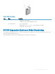
4 SC460 Expansion Enclosure Technical Specifications This appendix contains the technical specifications for the SC460 expansion enclosure. Technical Specifications The technical specifications of the SC460 expansion enclosure are displayed in the following tables. Drives SAS hard drives Dell Enterprise Plus drives Up to 60 hot-swappable 7.2K RPM 12 Gbps 3.
Environmental Temperature Operating 5° to 40°C (41° to 104°F) with a maximum temperature gradation of 10°C per hour Storage -40° to 65°C (-40° to 149°F) with a maximum temperature gradation of 25°C per hour Relative humidity Operating 20% to 80% (noncondensing) Storage 10% to 90% (noncondensing) Altitude Operating -16 to 2300 m (-50 to 7500 ft) Storage -16 to 10,600 m (-50 to 35,000 ft) SC460 Expansion Enclosure Technical Specifications 67