Industrial Slim Type Fast Ethernet Rail Switch 505710 / 505628 Series User’s Manual Version 1.0 May, 2008.
\ 505710 / 505628 Series User’s Manual Table of Content Overview .........................................................................................................2 1.1 About the 505710 / 505628 unmanaged Industrial Switch...........................................2 1.2 Hardware Features.............................................................................................................2 Hardware Installation...............................................................................
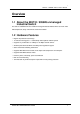
\ 505710 / 505628 Series User’s Manual Overview 1.1 About the 505710 / 505628 unmanaged Industrial Switch The 505710 / 505628 series are reliable unmanaged industrial switches which can work under wide temperature, dusty environment and humid condition. 1.
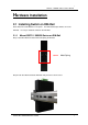
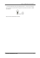
\ 505710 / 505628 Series User’s Manual Hardware Installation 2.1 Installing Switch on DIN-Rail Each switch has a DIN-Rail kit on rear panel. The DIN-Rail kit helps switch to fix on the DIN-Rail. It is easy to install the switch on the DIN-Rail: 2.1.1 Mount 505710 / 505628 Series on DIN-Rail Step 1: Slant the switch and mount the metal spring to DIN-Rail. Metal Spring Step 2: Push the switch toward the DIN-Rail until you heard a “click” sound.
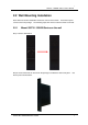
\ 505710 / 505628 Series User’s Manual 2.2 Wall Mounting Installation Each switch has another installation method for users to fix the switch. A wall mount panel can be found in the package. The following steps show how to mount the switch on the wall. 2.2.1 Mount 505710 / 505628 Series on the wall Step 1: Remove DIN-Rail kit. Step 2: Use 6 screws that can be found in the package to combine the wall mount panel.
\ 505710 / 505628 Series User’s Manual The screws specification shows in the following two pictures. In order to prevent switches from any damage, the screws should not larger than the size that used in 505710 / 505628 series switches. Pozidrive Step 3: Mount the combined switch on the wall.
\ 505710 / 505628 Series User’s Manual Hardware Overview 3.1 Front Panel The following table describes the labels that stick on the IES-1080 / 1062 series. Port Description 10/100 RJ-45 fast 10/100Base-T(X) RJ-45 fast Ethernet ports support Ethernet ports auto-negotiation.
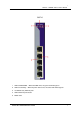
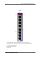
\ 505710 / 505628 Series User’s Manual 505710 1. LED for PWR1&PW2. When the PWR1 links, the green led will be light on. 2. LED for Fault Relay. When the power fault occurs, the amber LED will be light on. 3. 10/100Base-T(X) Ethernet ports. 4. LED for Ethernet ports status. 5.
\ 505710 / 505628 Series User’s Manual 505628 1. LED for PWR1&PW2. When the PWR1 links, the green led will be light on. 2. LED for Fault Relay. When the power fault occurs, the amber LED will be light on. 3. 10/100Base-T(X) Ethernet ports. 4. LED for Ethernet ports status. 5.
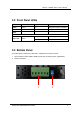
\ 505710 / 505628 Series User’s Manual 3.2 Front Panel LEDs LED Color Status Description PWR1 Green On DC power module 1 activated. PWR2 Green On DC power module 2 activated. Fault Amber On Fault relay. Power failure. 10/100Base-T(X) Fast Ethernet ports LNK / ACT Green On Port link up. Blinking Data transmitted. 3.3 Bottom Panel The bottom panel components of IES-1080 / 1062 Series are shown as below: 1. Terminal block includes: PWR1, PWR2 (12-48V DC) and Relay output (1A@24VDC). 2.
\ 505710 / 505628 Series User’s Manual 3.4 Rear Panel The components in the rare of IES-1080 / 1062 Series are shown as below: 1. Screw holes for wall mount kit. 2.
\ 505710 / 505628 Series User’s Manual Cables 4.1 Ethernet Cables The 505710 / 505628 series switches have standard Ethernet ports. According to the link type, the switches use CAT 3, 4, 5,5e UTP cables to connect to any other network device (PCs, servers, switches, routers, or hubs). Please refer to the following table for cable specifications. Cable Types and Specifications Cable Type Max. Length Connector 10BASE-T Cat.3, 4, 5 100-ohm UTP 100 m (328 ft) RJ-45 100BASE-TX Cat.
\ 505710 / 505628 Series User’s Manual Pin Number MDI port MDI-X port 1 TD+(transmit) RD+(receive) 2 TD-(transmit) RD-(receive) 3 RD+(receive) TD+(transmit) 4 Not used Not used 5 Not used Not used 6 RD-(receive) TD-(transmit) 7 Not used Not used 8 Not used Not used Note: “+” and “-” signs represent the polarity of the wires that make up each wire pair.
\ 505710 / 505628 Series User’s Manual Power Redundant Input power Power consumption (Typ.) Overload current protection Reverse polarity protection Dual DC inputs. 12-48VDC on 6-pin terminal block. 4 Watts 3.5 Watts Present Present Physical Characteristic Enclosure Dimension (W x D x H) Weight (g) IP-30 33(W) x 95(D) x 144.3(H) mm (1.30 x 3.74 x 5.68 inch.
\ 505710 / 505628 Series User’s Manual INTELLINET NETWORK SOLUTIONS™ offers a complete line of active and passive networking products. Ask your local computer dealer for more information or visit www.intellinet-network.com Copyright © INTELLINET NETWORK SOLUTIONS All products mentioned are trademarks or registered trademarks of their respective owners.