
Reference Manual

16-Axis MACRO CPU Software Reference Manual
16-Axis MACRO Station MI-Variable Reference 15
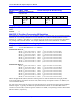
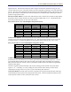
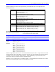
$30 ($B0) Triple-Byte Parallel (24 bits) in
middle bytes of 24-bit words
Used for ACC-3E parallel feedback;
Middle byte is at {address + 1};
Most significant byte is at {address + 2}
$31 ($B1) 16-Bit Parallel in high 16 bits of
24 bit word
Used for ACC-28B A/D converter feedback
$32 ($B2) Double 13-Bit Parallel Used for Sanyo Absolute Encoder Interface
$33 ($B3) 12-Bit Parallel in high 12 bits of
24-bit word
Used for ACC-1E-B2 or ACC-6E A/D converter
feedback
$48-$56
($C8-$D6)
Single-X-Word Parallel (8 to 24
bits)
Value in B16-23 is number of bits to read
$57-$6A
($D7-$EA)
Double-X-Word Parallel (25 to
42 bits)
Value in B16-23 is number of bits; most
significant bits are at {address + 1}
$71 ($F1) Yaskawa Absolute Encoder
Converter thru Multiplexer Port
Used for ACC-8D Opt 9 connected to CPU board
JTHW port; address is multiplexer port address
($00 - $FF)
$72 ($F2) Yaskawa Absolute Encoder
Converter thru RS-232 interface
Used for ACC-8D Opt 9 connected to CPU board
serial port.
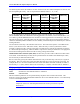
If Bit 23 of MI11x is set to 1 (providing the value for Bits 16-23 shown in parentheses), then the position
value read is sign extended to produce a signed position value. If Bit 23 is set to 0, no sign extension is
performed, producing an unsigned positive position value. Bit 23 of PMAC’s Ix10 for the motor using
this MACRO node must be the same as Bit 23 of the Station’s MI11x.
MS{anynode},MI119 (Reserved for Future Use)
MS{anynode},MI120-MI151 Encoder Conversion Table Entries
Range: $000000 - $FFFFFF
Units: Extended 16-Axis MACRO Station Addresses
Default: (dependent on SW1 setting)
MI120 through MI151 form the 32-setup lines of the 16-axis MACRO Station’s Encoder Conversion
Table (ECT). The Encoder Conversion Table on the Station is similar in concept to that of the PMAC or
PMAC2 itself; it is identical in structure to the Encoder Conversion Table of the Turbo PMAC. The 16-
axis MACRO Station’s table is executed every ring cycle to prepare the feedback data to be sent back to
the PMAC over the MACRO ring, where it will likely be passed through the PMAC’s own table.
The ECT consists of a series of entries with each entry processing one feedback value. An entry in the
ECT can have one, two, or three lines, therefore one, two, or three of these 24-bit MI-variables. Each MI-
variable occupies a fixed register in the 16-axis MACRO Station’s memory map. The register addresses
are important, because the results of the ECT are accessed by address.
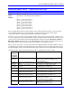
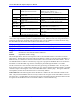
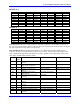
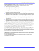
Table Addresses: The following table shows the Station Y-address for each of the MI-variables in the
table. The processed feedback value for an entry resides in the X-register of the same address as the last
line of the entry. Variable MI10x for the xth motor node on the Station should contain the address of this
X-register for the feedback it wants to send back to PMAC over the MACRO ring.