
Reference Manual

16-Axis MACRO CPU Software Reference Manual
20 16-Axis MACRO Station MI-Variable Reference
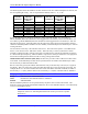
Parallel Feedback Entries ($2x, $3x, $6x, $7x): The parallel feedback entries read a word from the
address specified in the low 16 bits of the first entry. The four methods in this class are:
• $2x: Y-word parallel, no filtering (2-line entry)
• $3x: Y-word parallel, with filtering (3-line entry)
• $6x: X-word parallel, no filtering (2-line entry)
• $7x: X-word parallel, with filtering (3-line entry)
The second digit in the first line of the entry, represented above by ‘x’, specifies how the parallel data at
the specified address is to be processed. Currently there are 5 valid values of ‘x’:
• x=0: Shift data so that the least significant bit of the source register as specified in the “bits used”
mask word is placed in bit 5 of the processed result.
• x=4: Read the least significant byte from the low byte of the specified address; read the middle byte
from the low byte of the (specified address + 1); read the most significant byte from the low byte of
the (specified address + 2). This is used for feedback brought in through the ACC-14E 48-I/O board.
• x=5: Read the least significant byte from the middle byte of the specified address; read the middle
byte from the middle byte of the (specified address + 1); read the most significant byte from the
middle byte of the (specified address + 2). This is used for feedback brought in through the ACC-
14E 48-I/O board.
• x=6: Read the least significant byte from the high byte of the specified address; read the middle byte
from the high byte of the (specified address + 1); read the most significant byte from the high byte of
the (specified address + 2). This is used for feedback brought in through the ACC-14E 48-I/O board.
• x=8: Process the data from the source register without any shifting, so the least significant bit of the
source register as specified in the “bits used” mask word is place in bit 0 of the processed result.
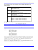
Time Base Entries ($4x): A time-base entry performs a scaled digital differentiation of the value in the
source register. It is a two-line entry. The first line contains a ‘4’ in the first hex digit and the address of
the source register in the last four hex digits. Usually, the source register is the result register of an
incremental encoder entry higher in the table (addresses $0020 to $003F).
The second line in the entry is the time-base scale factor. The result value equals 2 * Time-Base-Scale-
Factor * (New Source Value - Old Source Value). When this entry is used to synchronize a motion
program to a master encoder, creating an electronic cam function, this scale factor should be set equal to
2
17
/ Real-Time-Input-Frequency, where the RTIF is expressed in counts per millisecond. The program is
then written if the master encoder is always putting out this RTIF.
Triggered Time Base Entries ($9x, $Ax, $Bx): A triggered time-base entry is like a regular time-base
entry, except that it is easy to freeze the time base, then start it exactly on receipt of a trigger that captures
the starting master position or time.
The source register for triggered time base must be the starting (X) address for one of the machine
interface channels on the Station.