
User's Manual

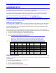

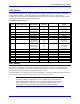
Table Of Contents
- 16-Axis MACRO Slave Station Binding to a MACRO Master
- Mapping Servo Channels to Servo Node
- Mapping Motor Node Registers
- Mapping Motor Function Registers to Node Registers
- Mapping of General Purpose I/O
- UMAC (Pack) Configuration
- I/O Accessory Boards
- Auto Configuration and Identification of UMAC (Pack) Boards
- UMAC (Pack) Interface/Breakout Boards
- MACRO Ring Rules
- I7: Phase Cycle Extension
- I19: Clock Source I-Variable Number
- Turbo PMAC2 Ultralite: I6800 and I6801
- UMAC Turbo
- Notes on Servo Clock
- I6840: MACRO IC 0 Master Configuration
- I6890/I6940/I6990: MACRO IC 1/2/3 Master Configuration
- I6841/I6891/I6941/I6991: MACRO IC 0/1/2/3 Node Activation Control
- I70/I72/I74/I76: MACRO IC 0/1/2/3 Node Auxiliary Function Enable
- I71/I73/I75/I77: MACRO IC 0/1/2/3 Node Protocol Type Control
- I78: MACRO Master/Slave Auxiliary Communications Timeout
- I79: MACRO Master/Master Auxiliary Communications Timeout
- I80, I81, I82: MACRO Ring Check Period and Limits
- Ixx01: Commutation Enable
- Ixx02: Command Output Address
- Ixx03, Ixx04: Feedback Address
- Ixx10, Ixx95: Absolute Position Address and Format
- Ixx25, Ixx24: Flag Address and Mode
- Ixx70, Ixx71: Commutation Cycle Size
- Ixx75: Absolute Phase Position Offset
- Ixx81, Ixx91: Power-On Phase Position Address and Mode
- Ixx82: Current Loop Feedback Address
- Ixx83: Commutation Feedback Address
- Ring Update Frequency
- Station Servo Clock Frequency
- MACRO IC 0
- MACRO IC 1
- MACRO IC 0
- MACRO IC 1
- Channels 1-4 (First 4-Axis Board)
- Channels 5-8 (Second 4-Axis Board)
- On Board Auxiliary Channels (Handwheel/Pulse and Direction)
- Incremental Digital Encoder Feedback
- Analog Encoder Feedback
- Resolver Feedback
- MLDT Feedback
- 12-Bit A/D Converter Feedback
- 14E Parallel Feedback
- MI17 Amplifier Fault Disable Control
- MI18 Amplifier Fault Polarity Control
- MI10x Position Feedback Address
- MI11x Power-On Position Feedback Address
- MI16x Power-On MLDT Excitation Value
- MI975 I/O Node Enable
- MI19 I/O Transfer Period
- Bi-Directional I/O Transfer Control
- Uni-Directional I/O Transfer Control
- Setting the Trigger Condition
- Using for Homing
- Using in User Program
- Setting up for a Single Pulse Output
- Setting up for Multiple Pulse Outputs
- How to Enable and Disable MACRO ASCII Communication Mode
- The Ring Order Method
- Example: Read Using MM-Variables – Actual Encoder
- Example: Read DAC Output from Servo IC Card
- Example: Monitor Up/Down Counter from Servo IC Card
- Example: Write to DACnB on Servo IC Card
- Example: Read Using MI198 and MI199 – Direct Hal
- Example: Read Using MI198 and MI199 – Actual DAC

16-Axis MACRO CPU User Manual
Hardware Setup 7
HARDWARE SETUP
The hardware setup of the 16-Axis MACRO CPU for the UMAC MACRO 16x is covered in the
Hardware Reference manual for the 3U 16-Axis MACRO CPU Board and the manuals for each of the
individual accessory boards in the station. A brief summary is given here.
The electronic hardware of a 16-Axis MACRO CPU consists of a 3U 16-Axis MACRO CPU Interface
board that contains the MACRO link to the ring and the processor that governs the operation of the
Station, plus some combination of axis interface boards and I/O interface boards.
Physical and Logical Configuration of the MACRO Station
This section briefly describes how the boards in a MACRO Station interface together and how they
communicate – what addresses they occupy in the address space of the MACRO CPU. More details are
given in the manuals for each specific board.
UMAC (Pack) Configuration
In the UMAC (Pack) configuration, the Axis-interface boards and the I/O-interface boards communicate
to the MACRO CPU board via an Acc-Ux Ubus backplane board. Each board can slide into a standard
3U rack with 4T (20mm, 0.8”) spacing between boards and connect physically to the backplane board.
Servo Accessory Boards
For servo interface, the 16-Axis MACRO CPU board can address up to four servo interface/breakout
accessory boards on the UMAC backplane. The boards in this family that are presently available include:
• Acc-24E2 2/4-channel PWM servo interface/breakout board
• Acc-24E2A 2/4-channel analog servo interface/breakout board
• Acc-24E2S 4-channel stepper/encoder interface/breakout board
• Acc-51E high-resolution encoder-interpolator board
Note:
Option 1A or Option 1D on the Acc-24E2 or Acc-24E2A, while it adds an extra
physical slot, does not count as an extra accessory board for addressing purposes.
The addresses and channel numbers on these boards are set by Dip switch S1.
S1-1 S1-2 S1-3 S1-4 S1-5 S1-6 Servo IC # Board Base
Address
ON ON ON ON ON ON 1 $8000
OFF ON ON ON ON ON 2 $8040
ON ON OFF ON ON ON 3 $9000
OFF ON OFF ON ON ON 4 $9040
ON ON ON OFF ON ON 5 $A000
OFF ON ON OFF ON ON 6 $A040
ON ON OFF OFF ON ON 7 $B000
OFF ON OFF OFF ON ON 8 $B040
I/O Accessory Boards
For I/O interface, the MACRO CPU board can address accessory boards at four different addresses on the
backplane. The addresses on these boards are set by jumpers on some accessory boards and Dip switches
on other boards.
The I/O boards whose addresses are set by jumpers are:
• Acc-9E isolated 48 input board
• Acc-10E isolated 48 output board
• Acc-11E isolated 24 In/24 out board
• Acc-12E isolated 24 In/24 high-power out board