
User's Manual
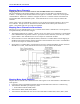
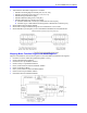

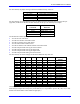

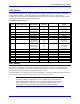
Table Of Contents
- 16-Axis MACRO Slave Station Binding to a MACRO Master
- Mapping Servo Channels to Servo Node
- Mapping Motor Node Registers
- Mapping Motor Function Registers to Node Registers
- Mapping of General Purpose I/O
- UMAC (Pack) Configuration
- I/O Accessory Boards
- Auto Configuration and Identification of UMAC (Pack) Boards
- UMAC (Pack) Interface/Breakout Boards
- MACRO Ring Rules
- I7: Phase Cycle Extension
- I19: Clock Source I-Variable Number
- Turbo PMAC2 Ultralite: I6800 and I6801
- UMAC Turbo
- Notes on Servo Clock
- I6840: MACRO IC 0 Master Configuration
- I6890/I6940/I6990: MACRO IC 1/2/3 Master Configuration
- I6841/I6891/I6941/I6991: MACRO IC 0/1/2/3 Node Activation Control
- I70/I72/I74/I76: MACRO IC 0/1/2/3 Node Auxiliary Function Enable
- I71/I73/I75/I77: MACRO IC 0/1/2/3 Node Protocol Type Control
- I78: MACRO Master/Slave Auxiliary Communications Timeout
- I79: MACRO Master/Master Auxiliary Communications Timeout
- I80, I81, I82: MACRO Ring Check Period and Limits
- Ixx01: Commutation Enable
- Ixx02: Command Output Address
- Ixx03, Ixx04: Feedback Address
- Ixx10, Ixx95: Absolute Position Address and Format
- Ixx25, Ixx24: Flag Address and Mode
- Ixx70, Ixx71: Commutation Cycle Size
- Ixx75: Absolute Phase Position Offset
- Ixx81, Ixx91: Power-On Phase Position Address and Mode
- Ixx82: Current Loop Feedback Address
- Ixx83: Commutation Feedback Address
- Ring Update Frequency
- Station Servo Clock Frequency
- MACRO IC 0
- MACRO IC 1
- MACRO IC 0
- MACRO IC 1
- Channels 1-4 (First 4-Axis Board)
- Channels 5-8 (Second 4-Axis Board)
- On Board Auxiliary Channels (Handwheel/Pulse and Direction)
- Incremental Digital Encoder Feedback
- Analog Encoder Feedback
- Resolver Feedback
- MLDT Feedback
- 12-Bit A/D Converter Feedback
- 14E Parallel Feedback
- MI17 Amplifier Fault Disable Control
- MI18 Amplifier Fault Polarity Control
- MI10x Position Feedback Address
- MI11x Power-On Position Feedback Address
- MI16x Power-On MLDT Excitation Value
- MI975 I/O Node Enable
- MI19 I/O Transfer Period
- Bi-Directional I/O Transfer Control
- Uni-Directional I/O Transfer Control
- Setting the Trigger Condition
- Using for Homing
- Using in User Program
- Setting up for a Single Pulse Output
- Setting up for Multiple Pulse Outputs
- How to Enable and Disable MACRO ASCII Communication Mode
- The Ring Order Method
- Example: Read Using MM-Variables – Actual Encoder
- Example: Read DAC Output from Servo IC Card
- Example: Monitor Up/Down Counter from Servo IC Card
- Example: Write to DACnB on Servo IC Card
- Example: Read Using MI198 and MI199 – Direct Hal
- Example: Read Using MI198 and MI199 – Actual DAC

16-Axis MACRO CPU User Manual
Turbo PMAC2 Software Setup for MACRO Station 11
TURBO PMAC2 SOFTWARE SETUP FOR MACRO STATION
Setting up the Turbo PMAC2 board to work with a MACRO Station requires the proper setup of several
I-Variables for MACRO-specific features. The variables that have special considerations for use with
MACRO stations are listed below.
Note:
These are I-Variables on the Turbo PMAC2 controller itself. The MACRO Station
has its own set of setup I- Variables, called MI-Variables, which are detailed in a
different section.
Typically, the Turbo Setup program for PCs is used to set up these I-Variables.
MACRO IC Address Specification
Turbo PMAC2 firmware provides automatic support for up to four MACRO ICs at one time, known as
MACRO ICs 0, 1, 2, and 3. Prior to firmware revision V1.936, each of these four ICs had a fixed base
address: $078400 for MACRO IC 0, $079400 for MACRO IC 1, $07A400 for MACRO IC 2, and
$07B400 for MACRO IC 3.
Turbo PMAC2 boards without a built-in MACRO interface support only MACRO IC 0 at the fixed
address of $078400. Turbo PMAC2 Ultralite boards can also support MACRO ICs 1, 2, and 3 if the
appropriate options are ordered:
• Option 1U1: MACRO IC 1 at $079400
• Option 1U2: MACRO IC 2 at $07A400
• Option 1U3: MACRO IC 3 at $07B400
The introduction of the UMAC Turbo (3U Turbo PMAC2) allowed more possibilities for addressing
MACRO ICs which requires a more flexible firmware structure. Therefore, starting in Turbo PMAC2
firmware revision V1.936, variables I20, I21, I22, and I23 are used to specify the base addresses of
MACRO ICs 0, 1, 2, and 3, respectively. Usually, these will be at the default values of $078400,
$079400, $07A400, and 07B400, but other values are possible in a UMAC Turbo system with multiple
Acc-5E MACRO interface boards.
MACRO Ring Update Frequency Setup
The discussions of MACRO node addresses below all assume that I20, I21, I22, and I23 are set to their
factory default values.
All stations on the MACRO ring must be set to the same ring update frequency. The ring update
frequency is controlled fundamentally by the ring controller or synchronizing master. The ring update
frequency is the same as the hardware phase clock frequency on the card. The synchronizing master
initiates the start of the MACRO ring cycle. When it has finished sending its data, the control of the ring
is passed to the next non-synchronizing master. This is done until there are no non-synchronizing
masters. Then the ring goes quiet with no data being sent. Each MACRO slave exchanges data with its
master when it satisfies the Master Address and Node enable check. This is determined by bits 0-15 and
20-23 in the MACRO stations MI996 and the Turbo PMACs I6841, I6891, I6941 and I6991.
MACRO Ring Rules
1. Only one synchronizing master can be on the ring. This is bit 4=1 and 5=1 of the Turbo PMAC’s
I6840. Set I6890, I6940, and I6990 bit 4=1 and bit 5=0 for them to be non-synchronizing masters or
bit 4=0 and bit 5=0, if will not be sending data on the ring. As an exception to this rule, upon a ring
break, a MACRO slave station becomes a synchronizing master to send ring break information to its
following stations on the ring. To allow MACRO ASCII Communication Mode, bit 14 of I6840 at
the Ultralite or Master must be set to one and bit 14 of MI996 at the MACRO CPU must be set. The
Ultralite will read this bit at power-up and therefore this parameter must be saved to the Ultralite and
then restarted at least once to enable the MACRO ASCII Communication Mode.