
User's Manual
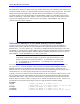
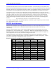
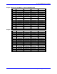

Table Of Contents
- 16-Axis MACRO Slave Station Binding to a MACRO Master
- Mapping Servo Channels to Servo Node
- Mapping Motor Node Registers
- Mapping Motor Function Registers to Node Registers
- Mapping of General Purpose I/O
- UMAC (Pack) Configuration
- I/O Accessory Boards
- Auto Configuration and Identification of UMAC (Pack) Boards
- UMAC (Pack) Interface/Breakout Boards
- MACRO Ring Rules
- I7: Phase Cycle Extension
- I19: Clock Source I-Variable Number
- Turbo PMAC2 Ultralite: I6800 and I6801
- UMAC Turbo
- Notes on Servo Clock
- I6840: MACRO IC 0 Master Configuration
- I6890/I6940/I6990: MACRO IC 1/2/3 Master Configuration
- I6841/I6891/I6941/I6991: MACRO IC 0/1/2/3 Node Activation Control
- I70/I72/I74/I76: MACRO IC 0/1/2/3 Node Auxiliary Function Enable
- I71/I73/I75/I77: MACRO IC 0/1/2/3 Node Protocol Type Control
- I78: MACRO Master/Slave Auxiliary Communications Timeout
- I79: MACRO Master/Master Auxiliary Communications Timeout
- I80, I81, I82: MACRO Ring Check Period and Limits
- Ixx01: Commutation Enable
- Ixx02: Command Output Address
- Ixx03, Ixx04: Feedback Address
- Ixx10, Ixx95: Absolute Position Address and Format
- Ixx25, Ixx24: Flag Address and Mode
- Ixx70, Ixx71: Commutation Cycle Size
- Ixx75: Absolute Phase Position Offset
- Ixx81, Ixx91: Power-On Phase Position Address and Mode
- Ixx82: Current Loop Feedback Address
- Ixx83: Commutation Feedback Address
- Ring Update Frequency
- Station Servo Clock Frequency
- MACRO IC 0
- MACRO IC 1
- MACRO IC 0
- MACRO IC 1
- Channels 1-4 (First 4-Axis Board)
- Channels 5-8 (Second 4-Axis Board)
- On Board Auxiliary Channels (Handwheel/Pulse and Direction)
- Incremental Digital Encoder Feedback
- Analog Encoder Feedback
- Resolver Feedback
- MLDT Feedback
- 12-Bit A/D Converter Feedback
- 14E Parallel Feedback
- MI17 Amplifier Fault Disable Control
- MI18 Amplifier Fault Polarity Control
- MI10x Position Feedback Address
- MI11x Power-On Position Feedback Address
- MI16x Power-On MLDT Excitation Value
- MI975 I/O Node Enable
- MI19 I/O Transfer Period
- Bi-Directional I/O Transfer Control
- Uni-Directional I/O Transfer Control
- Setting the Trigger Condition
- Using for Homing
- Using in User Program
- Setting up for a Single Pulse Output
- Setting up for Multiple Pulse Outputs
- How to Enable and Disable MACRO ASCII Communication Mode
- The Ring Order Method
- Example: Read Using MM-Variables – Actual Encoder
- Example: Read DAC Output from Servo IC Card
- Example: Monitor Up/Down Counter from Servo IC Card
- Example: Write to DACnB on Servo IC Card
- Example: Read Using MI198 and MI199 – Direct Hal
- Example: Read Using MI198 and MI199 – Actual DAC

16-Axis MACRO CPU User Manual
14 Turbo PMAC2 Software Setup for MACRO Station
Even if the Turbo PMAC2 controller is not performing commutation or current-loop closure, and therefore
not performing any software tasks at the Phase clock frequency, the Phase clock frequency should if possible
be set to at least twice the Servo clock frequency. Because the MACRO ring data is transmitted at the Phase
clock frequency, the over sampling of ring servo data that results, eliminates one servo cycle’s delay in
transmission of servo loop data, which permits higher servo gains and better performance.
Turbo PMAC2 MACRO Ring Setup I-Variables
I6840: MACRO IC 0 Master Configuration
Any MACRO IC on a Turbo PMAC2 talking to a MACRO Station must be configured as a master on the
ring. For purposes of the MACRO protocol, each MACRO IC is a separate logical master with its own
master number, even though there may be multiple MACRO ICs on a single physical Turbo PMAC2.
Each ring must have one and only one ring controller (synchronizing master). This should be the
MACRO IC 0 of the Turbo PMAC2 boards on the ring.
On a Turbo PMAC2, I6840 should be set to $4030 to make the card’s MACRO IC 0 the ring controller and
enable the MACRO ASCII Communication feature. This sets bits 4, 5, and 14 of the variable to 1. Setting
bit 4 to 1 makes the IC a master on the ring; setting bit 5 to 1, makes the IC the ring controller starting each
ring cycle by itself and setting bit 14 to 1 enables the MACRO ASCII Communication feature.
On a Turbo PMAC2 whose MACRO IC 0 will be a master but not ring controller, I6840 should be set to
$90. This sets bits 4 and 7 of the variable to 1. Setting bit 4 to 1 makes the IC a master on the ring. Use
MACRO Ring Rules for setting bit 7 to 1, which causes this IC to be synchronized to the ring controller IC
every time it receives a ring packet specified by I6841. If not using the MACRO IC, set its corresponding I-
variable to zero.
I6890/I6940/I6990: MACRO IC 1/2/3 Master Configuration
A Turbo PMAC2 Ultralite may have additional MACRO ICs if Options 1U1, 1U2, and/or 1U3 are
ordered. A UMAC Turbo system may have additional MACRO ICs if Option 1 on an Acc-5E is ordered,
or if multiple Acc-5E boards are ordered. These additional ICs should be set to be masters but not ring
controllers by setting I6890, I6940, and I6990, respectively to $10. This sets bit 4 of the variable to 1,
making the IC a master on the ring. Use MACRO Ring Rules for setting up these ICs.
I6841/I6891/I6941/I6991: MACRO IC 0/1/2/3 Node Activation Control
I6841, I6891, I6941, and I6991 on Turbo PMAC2 control which of the 16 MACRO nodes for MACRO
ICs 0, 1, 2, and 3, respectively, on the card are activated. They also control the master station number for
their respective ICs and the node number of the packet that creates a synchronization signal. The bits of
these I-variables are arranged as follows:
Bits 0-15: Activation of MACRO Nodes 0 to 15, respectively (1 = active, 0 = inactive). These 16 bits
(usually read as four hex digits) individually control the activation of the MACRO nodes in the MACRO
IC on a Turbo PMAC2. Each node that is active on the matching MACRO Station, whether for servo,
I/O, or auxiliary communications, should have its node activation bit set to 1. When working with a
MACRO Station, Node 15 of each MACRO IC on a Turbo PMAC2 must be activated to permit auxiliary
communications, so bit 15 of this variable should always be set to 1 if the IC is used to communicate with
a MACRO Station. Node 14 of MACRO IC0 enables the MACRO ASCII Communication feature.
Bits 16-19: Packet Sync Node Slave Number. These four bits together (usually read as one hex digit)
form the slave number (0 to 15) of the packet whose receipt by the PMAC2 will set the Sync Packet
Received status bit in the MACRO IC. Usually, this digit is set to $F (15) because Node 15 is always
activated and it is the last node transmitted. If it is the Sync Packet, then the phase clock will be
resynched after all the ring data is in the MACRO registers. This is critical only on the MACRO IC that
is the source of the phase clock. Its synch node phase lock bit must be set on this MACRO IC.
Bits 20-23: Master Number. These four bits together form the master number (0 to 15) of the MACRO
IC on the MACRO ring.