
User's Manual
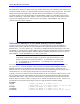
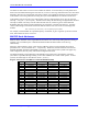

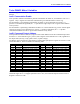
Table Of Contents
- 16-Axis MACRO Slave Station Binding to a MACRO Master
- Mapping Servo Channels to Servo Node
- Mapping Motor Node Registers
- Mapping Motor Function Registers to Node Registers
- Mapping of General Purpose I/O
- UMAC (Pack) Configuration
- I/O Accessory Boards
- Auto Configuration and Identification of UMAC (Pack) Boards
- UMAC (Pack) Interface/Breakout Boards
- MACRO Ring Rules
- I7: Phase Cycle Extension
- I19: Clock Source I-Variable Number
- Turbo PMAC2 Ultralite: I6800 and I6801
- UMAC Turbo
- Notes on Servo Clock
- I6840: MACRO IC 0 Master Configuration
- I6890/I6940/I6990: MACRO IC 1/2/3 Master Configuration
- I6841/I6891/I6941/I6991: MACRO IC 0/1/2/3 Node Activation Control
- I70/I72/I74/I76: MACRO IC 0/1/2/3 Node Auxiliary Function Enable
- I71/I73/I75/I77: MACRO IC 0/1/2/3 Node Protocol Type Control
- I78: MACRO Master/Slave Auxiliary Communications Timeout
- I79: MACRO Master/Master Auxiliary Communications Timeout
- I80, I81, I82: MACRO Ring Check Period and Limits
- Ixx01: Commutation Enable
- Ixx02: Command Output Address
- Ixx03, Ixx04: Feedback Address
- Ixx10, Ixx95: Absolute Position Address and Format
- Ixx25, Ixx24: Flag Address and Mode
- Ixx70, Ixx71: Commutation Cycle Size
- Ixx75: Absolute Phase Position Offset
- Ixx81, Ixx91: Power-On Phase Position Address and Mode
- Ixx82: Current Loop Feedback Address
- Ixx83: Commutation Feedback Address
- Ring Update Frequency
- Station Servo Clock Frequency
- MACRO IC 0
- MACRO IC 1
- MACRO IC 0
- MACRO IC 1
- Channels 1-4 (First 4-Axis Board)
- Channels 5-8 (Second 4-Axis Board)
- On Board Auxiliary Channels (Handwheel/Pulse and Direction)
- Incremental Digital Encoder Feedback
- Analog Encoder Feedback
- Resolver Feedback
- MLDT Feedback
- 12-Bit A/D Converter Feedback
- 14E Parallel Feedback
- MI17 Amplifier Fault Disable Control
- MI18 Amplifier Fault Polarity Control
- MI10x Position Feedback Address
- MI11x Power-On Position Feedback Address
- MI16x Power-On MLDT Excitation Value
- MI975 I/O Node Enable
- MI19 I/O Transfer Period
- Bi-Directional I/O Transfer Control
- Uni-Directional I/O Transfer Control
- Setting the Trigger Condition
- Using for Homing
- Using in User Program
- Setting up for a Single Pulse Output
- Setting up for Multiple Pulse Outputs
- How to Enable and Disable MACRO ASCII Communication Mode
- The Ring Order Method
- Example: Read Using MM-Variables – Actual Encoder
- Example: Read DAC Output from Servo IC Card
- Example: Monitor Up/Down Counter from Servo IC Card
- Example: Write to DACnB on Servo IC Card
- Example: Read Using MI198 and MI199 – Direct Hal
- Example: Read Using MI198 and MI199 – Actual DAC

16-Axis MACRO CPU User Manual
Turbo PMAC2 Software Setup for MACRO Station 15
Each MACRO IC acting as a master on the ring, whether on the same card or different cards, must have its
own master number and acts as a separate master station for the purposes of the ring protocol. This master
number forms half of the address byte with each packet sent by the PMAC2 over the MACRO ring.
The master number can be the same number as the MACRO IC number (e.g. MACRO IC 0 has master
number 0, MACRO IC 1 has master number 1, and so on), and if there is only one Turbo PMAC2 in the
ring, this will probably be the case. However, this is not required. The MACRO IC that is the ring
controller must have master number 0.
I70/I72/I74/I76: MACRO IC 0/1/2/3 Node Auxiliary Function Enable
I70, I72, I74, and I76 are 16-bit I-Variables (bits 0 - 15) in which each bit controls the enabling or
disabling of the auxiliary flag function for the MACRO node number matching the bit number for
MACRO ICs 0, 1, 2, and 3, respectively. A bit value of 1 enables the auxiliary flag function; a bit value
of 0 disables it. If the function is enabled, PMAC copies information automatically between the MACRO
interface flag register and RAM register $00344n, $00345n, $00346n, and $00347n (where n is the IC’s
node number 0 – 15) for MACRO ICs 0, 1, 2, and 3, respectively.
Note:
Turbo PMAC MACRO node numbers (as opposed to individual MACRO IC node
numbers) go from 0 to 63, with board nodes 0 – 15 on MACRO IC 0, board nodes
16 – 31 on MACRO IC 1, board nodes 32 – 47 on MACRO IC 2, and board nodes
48 – 63 on MACRO IC 3.
Each MACRO node n that is used for servo functions should have the corresponding bit n of I70, I72,
I74, or I76 set to 1. Ixx25 for the Motor x that uses Node n should then address $00344n, $00345n,
$00346n, or $00347n, not the address of the MACRO register itself (see below). If Register 3 of a
MACRO node n is used for other purposes, such as direct I/O, the corresponding bit n of I70, I72, I74, or
I76 should be set to 0, so this copying function does not overwrite these registers.
Typically, non-servo I/O functions with a MACRO Station do not involve auxiliary flag functions, so this
flag copy function should remain disabled for any node used to transmit I/O between the Turbo PMAC2
and the MACRO Station. If any auxiliary communications is done between the Turbo PMAC2 and the
MACRO Station on Nodes 14 and/or 15, bits 14 and 15 of these variables must be set to 0. However, on
the MACRO Acc-65M, the auxilary flags are used so its flag transfer bits would be enabled.
Examples:
I70=$3 ; Enabled for MACRO IC 0 Nodes 0 and 1
I70=$7 ; Enable Nodes 0 & 1 for servo control & 2 for Acc 65M
I72=$30 ; Enabled for MACRO IC 1 Nodes 4 and 5
I74=$3300 ; Enabled for MACRO IC 2 Nodes 8,9,12, and 13
I76=$3333 ; Enabled for MACRO IC 3 Nodes 0,1,4,5,8,9,12, and 13