
User's Manual
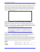
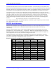
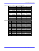
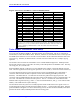
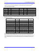

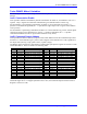
Table Of Contents
- 16-Axis MACRO Slave Station Binding to a MACRO Master
- Mapping Servo Channels to Servo Node
- Mapping Motor Node Registers
- Mapping Motor Function Registers to Node Registers
- Mapping of General Purpose I/O
- UMAC (Pack) Configuration
- I/O Accessory Boards
- Auto Configuration and Identification of UMAC (Pack) Boards
- UMAC (Pack) Interface/Breakout Boards
- MACRO Ring Rules
- I7: Phase Cycle Extension
- I19: Clock Source I-Variable Number
- Turbo PMAC2 Ultralite: I6800 and I6801
- UMAC Turbo
- Notes on Servo Clock
- I6840: MACRO IC 0 Master Configuration
- I6890/I6940/I6990: MACRO IC 1/2/3 Master Configuration
- I6841/I6891/I6941/I6991: MACRO IC 0/1/2/3 Node Activation Control
- I70/I72/I74/I76: MACRO IC 0/1/2/3 Node Auxiliary Function Enable
- I71/I73/I75/I77: MACRO IC 0/1/2/3 Node Protocol Type Control
- I78: MACRO Master/Slave Auxiliary Communications Timeout
- I79: MACRO Master/Master Auxiliary Communications Timeout
- I80, I81, I82: MACRO Ring Check Period and Limits
- Ixx01: Commutation Enable
- Ixx02: Command Output Address
- Ixx03, Ixx04: Feedback Address
- Ixx10, Ixx95: Absolute Position Address and Format
- Ixx25, Ixx24: Flag Address and Mode
- Ixx70, Ixx71: Commutation Cycle Size
- Ixx75: Absolute Phase Position Offset
- Ixx81, Ixx91: Power-On Phase Position Address and Mode
- Ixx82: Current Loop Feedback Address
- Ixx83: Commutation Feedback Address
- Ring Update Frequency
- Station Servo Clock Frequency
- MACRO IC 0
- MACRO IC 1
- MACRO IC 0
- MACRO IC 1
- Channels 1-4 (First 4-Axis Board)
- Channels 5-8 (Second 4-Axis Board)
- On Board Auxiliary Channels (Handwheel/Pulse and Direction)
- Incremental Digital Encoder Feedback
- Analog Encoder Feedback
- Resolver Feedback
- MLDT Feedback
- 12-Bit A/D Converter Feedback
- 14E Parallel Feedback
- MI17 Amplifier Fault Disable Control
- MI18 Amplifier Fault Polarity Control
- MI10x Position Feedback Address
- MI11x Power-On Position Feedback Address
- MI16x Power-On MLDT Excitation Value
- MI975 I/O Node Enable
- MI19 I/O Transfer Period
- Bi-Directional I/O Transfer Control
- Uni-Directional I/O Transfer Control
- Setting the Trigger Condition
- Using for Homing
- Using in User Program
- Setting up for a Single Pulse Output
- Setting up for Multiple Pulse Outputs
- How to Enable and Disable MACRO ASCII Communication Mode
- The Ring Order Method
- Example: Read Using MM-Variables – Actual Encoder
- Example: Read DAC Output from Servo IC Card
- Example: Monitor Up/Down Counter from Servo IC Card
- Example: Write to DACnB on Servo IC Card
- Example: Read Using MI198 and MI199 – Direct Hal
- Example: Read Using MI198 and MI199 – Actual DAC

16-Axis MACRO CPU User Manual
Turbo PMAC2 Software Setup for MACRO Station 17
The limits for these checks can be set with variables I81 and I82. If less than I82 sync node packets have
been received and detected during this time interval, or if I81 or more ring communications errors have been
detected in this interval, Turbo PMAC will assume a major ring problem and all motors will be shut down.
Turbo PMAC will set the global status bit Ring Error (bit 4 of X:$000006) as an indication of this error.
Turbo PMAC looks for receipt of sync node packets and ring communications errors once per real-time
interrupt – every (I8 + 1) servo cycles). The time interval set by I80 must be large enough that I82 real-time
interrupts in PMAC can always execute within the time interval, or false ring errors will be detected.
Remember that long motion program calculations can cause skips in the real-time interrupt. Typically,
values of I80 setting a time interval of about 20 milliseconds are used. I80 can be set according to the
formula:
I80 = Desired cycle time (msec) * Servo update frequency (kHz)
For example, with the default servo update frequency of 2.26 kHz, to get a ring check cycle interval of 20
msec, I80 would be set to 20 * 2.26 ≅ 45.
MACRO Node Addresses
The MACRO ring operates by copying registers at high speed across the ring. Therefore, each Turbo
PMAC2 master controller on the ring communicates with its slave stations by reading from and writing to
registers in its own address space. MACRO hardware handles the data transfers across the ring
automatically.
Starting in Turbo firmware version 1.936, the base addresses of the up to four MACRO ICs must be
specified in I20 – I23, for MACRO IC 0 – 3 respectively. Before this, the base addresses were fixed at
$078400, $079400, $07A400, and $07B400, respectively. Only UMAC Turbo systems can support any
other configuration, but only rarely will another configuration be used.
The following tables give the addresses of the MACRO ring registers for Turbo PMAC2 controllers.
(Note that it is possible, although unlikely, to have other addresses in a UMAC Turbo system. In these
systems, the fourth digit can also take the values 5, 6, and 7.)
Register Addresses for MACRO IC 0 with I20=$078400 (default)
Turbo PMAC2 Addresses MACRO IC 0
Node # Reg. 0 Reg. 1 Reg. 2 Reg. 3
0 Y:$078420 Y:$078421 Y:$078422 Y:$078423
1 Y:$078424 Y:$078425 Y:$078426 Y:$078427
2 X:$078420 X:$078421 X:$078422 X:$078423
3 X:$078424 X:$078425 X:$078426 X:$078427
4 Y:$078428 Y:$078429 Y:$07842A Y:$07842B
5 Y:$07842C Y:$07842D Y:$07842E Y:$07842F
6 X:$078428 X:$078429 X:$07842A X:$07842B
7 X:$07842C X:$07842D X:$07842E X:$07842F
8 Y:$078430 Y:$078431 Y:$078432 Y:$078433
9 Y:$078434 Y:$078435 Y:$078436 Y:$078437
10 X:$078430 X:$078431 X:$078432 X:$078433
11 X:$078434 X:$078435 X:$078436 X:$078437
12 Y:$078438 Y:$078439 Y:$07843A Y:$07843B
13 Y:$07843C Y:$07843D Y:$07843E Y:$07843F
14 X:$078438 X:$078439 X:$07843A X:$07843B
15 X:$07843C X:$07843D X:$07843E X:$07843F