
User's Manual
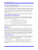
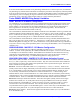
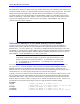
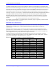
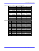
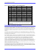
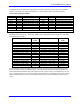

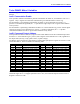
Table Of Contents
- 16-Axis MACRO Slave Station Binding to a MACRO Master
- Mapping Servo Channels to Servo Node
- Mapping Motor Node Registers
- Mapping Motor Function Registers to Node Registers
- Mapping of General Purpose I/O
- UMAC (Pack) Configuration
- I/O Accessory Boards
- Auto Configuration and Identification of UMAC (Pack) Boards
- UMAC (Pack) Interface/Breakout Boards
- MACRO Ring Rules
- I7: Phase Cycle Extension
- I19: Clock Source I-Variable Number
- Turbo PMAC2 Ultralite: I6800 and I6801
- UMAC Turbo
- Notes on Servo Clock
- I6840: MACRO IC 0 Master Configuration
- I6890/I6940/I6990: MACRO IC 1/2/3 Master Configuration
- I6841/I6891/I6941/I6991: MACRO IC 0/1/2/3 Node Activation Control
- I70/I72/I74/I76: MACRO IC 0/1/2/3 Node Auxiliary Function Enable
- I71/I73/I75/I77: MACRO IC 0/1/2/3 Node Protocol Type Control
- I78: MACRO Master/Slave Auxiliary Communications Timeout
- I79: MACRO Master/Master Auxiliary Communications Timeout
- I80, I81, I82: MACRO Ring Check Period and Limits
- Ixx01: Commutation Enable
- Ixx02: Command Output Address
- Ixx03, Ixx04: Feedback Address
- Ixx10, Ixx95: Absolute Position Address and Format
- Ixx25, Ixx24: Flag Address and Mode
- Ixx70, Ixx71: Commutation Cycle Size
- Ixx75: Absolute Phase Position Offset
- Ixx81, Ixx91: Power-On Phase Position Address and Mode
- Ixx82: Current Loop Feedback Address
- Ixx83: Commutation Feedback Address
- Ring Update Frequency
- Station Servo Clock Frequency
- MACRO IC 0
- MACRO IC 1
- MACRO IC 0
- MACRO IC 1
- Channels 1-4 (First 4-Axis Board)
- Channels 5-8 (Second 4-Axis Board)
- On Board Auxiliary Channels (Handwheel/Pulse and Direction)
- Incremental Digital Encoder Feedback
- Analog Encoder Feedback
- Resolver Feedback
- MLDT Feedback
- 12-Bit A/D Converter Feedback
- 14E Parallel Feedback
- MI17 Amplifier Fault Disable Control
- MI18 Amplifier Fault Polarity Control
- MI10x Position Feedback Address
- MI11x Power-On Position Feedback Address
- MI16x Power-On MLDT Excitation Value
- MI975 I/O Node Enable
- MI19 I/O Transfer Period
- Bi-Directional I/O Transfer Control
- Uni-Directional I/O Transfer Control
- Setting the Trigger Condition
- Using for Homing
- Using in User Program
- Setting up for a Single Pulse Output
- Setting up for Multiple Pulse Outputs
- How to Enable and Disable MACRO ASCII Communication Mode
- The Ring Order Method
- Example: Read Using MM-Variables – Actual Encoder
- Example: Read DAC Output from Servo IC Card
- Example: Monitor Up/Down Counter from Servo IC Card
- Example: Write to DACnB on Servo IC Card
- Example: Read Using MI198 and MI199 – Direct Hal
- Example: Read Using MI198 and MI199 – Actual DAC

16-Axis MACRO CPU User Manual
Turbo PMAC2 Software Setup for MACRO Station 21
The following table lists the conversion table entries to use these registers. Remember that the second
line of the entry should always be $018000:
Register First Line
Value
Register First Line
Value
Motor #1 Previous Phase Pos. $2800B2 Motor #17 Previous Phase Pos. $2808B2
Motor #2 Previous Phase Pos. $280132 Motor #18 Previous Phase Pos. $280932
Motor #3 Previous Phase Pos. $2801B2 Motor #19 Previous Phase Pos. $2809B2
Motor #4 Previous Phase Pos. $280232 Motor #20 Previous Phase Pos. $280A32
Motor #5 Previous Phase Pos. $2802B2 Motor #21 Previous Phase Pos. $280AB2
Motor #6 Previous Phase Pos. $280332 Motor #22 Previous Phase Pos. $280B32
Motor #7 Previous Phase Pos. $2803B2 Motor #23 Previous Phase Pos. $280BB2
Motor #8 Previous Phase Pos. $280432 Motor #24 Previous Phase Pos. $280C32
Motor #9 Previous Phase Pos. $2804B2 Motor #25 Previous Phase Pos. $280CB2
Motor #10 Previous Phase Pos. $280532 Motor #26 Previous Phase Pos. $280D32
Motor #11 Previous Phase Pos. $2805B2 Motor #27 Previous Phase Pos. $280DB2
Motor #12 Previous Phase Pos. $280632 Motor #28 Previous Phase Pos. $280E32
Motor #13 Previous Phase Pos. $2806B2 Motor #29 Previous Phase Pos. $280EB2
Motor #14 Previous Phase Pos. $280732 Motor #30 Previous Phase Pos. $280F32
Motor #15 Previous Phase Pos. $2807B2 Motor #31 Previous Phase Pos. $280FB2
Motor #16 Previous Phase Pos. $280832 Motor #32 Previous Phase Pos. $281032
Sometimes the conversion table will process data sent back to Turbo PMAC2 through I/O nodes, which
are mapped into Turbo PMAC2 as X-registers. Often this is done in cases of dual feedback or loop-
around-loop configurations. Because these I/O nodes use X-registers instead of Y-registers, they use the
$6 conversion method (X/Y data) instead of the $2 conversion method (Y data only) and specify a 24-bit
offset in the second line of the entry
The following table shows entries for processing the data in the 24-bit register 0 of the first six I/O nodes
for each MACRO IC:
Register First Line
Value
Register First Line
Value
MACRO IC 0 Node 2 Reg. 0 $6F8420 MACRO IC 2 Node 2 Reg. 0 $6FA420
MACRO IC 0 Node 3 Reg. 0 $6F8424 MACRO IC 2 Node 3 Reg. 0 $6FA424
MACRO IC 0 Node 6 Reg. 0 $6F8428 MACRO IC 2 Node 6 Reg. 0 $6FA428
MACRO IC 0 Node 7 Reg. 0 $6F842C MACRO IC 2 Node 7 Reg. 0 $6FA42C
MACRO IC 0 Node 10 Reg. 0 $6F8430 MACRO IC 2 Node 10 Reg. 0 $6FA430
MACRO IC 0 Node 11 Reg. 0 $6F8434 MACRO IC 2 Node 11 Reg. 0 $6FA434
MACRO IC 1 Node 2 Reg. 0 $6F9420 MACRO IC 3 Node 2 Reg. 0 $6FB420
MACRO IC 1 Node 3 Reg. 0 $6F9424 MACRO IC 3 Node 3 Reg. 0 $6FB424
MACRO IC 1 Node 6 Reg. 0 $6F9428 MACRO IC 3 Node 6 Reg. 0 $6FB428
MACRO IC 1 Node 7 Reg. 0 $6F942C MACRO IC 3 Node 7 Reg. 0 $6FB42C
MACRO IC 1 Node 10 Reg. 0 $6F9430 MACRO IC 3 Node 10 Reg. 0 $6FB430
MACRO IC 1 Node 11 Reg. 0 $6F9434 MACRO IC 3 Node 11 Reg. 0 $6FB434
The second line of one of these entries is $018018. The first 018 specifies a 24-bit width. The second
018 specifies a 24-bit offset from the Y-register’s bit 0, which puts the least significant bit used at the X-
register’s bit 0.