
User's Manual


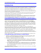
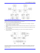
Table Of Contents
- 16-Axis MACRO Slave Station Binding to a MACRO Master
- Mapping Servo Channels to Servo Node
- Mapping Motor Node Registers
- Mapping Motor Function Registers to Node Registers
- Mapping of General Purpose I/O
- UMAC (Pack) Configuration
- I/O Accessory Boards
- Auto Configuration and Identification of UMAC (Pack) Boards
- UMAC (Pack) Interface/Breakout Boards
- MACRO Ring Rules
- I7: Phase Cycle Extension
- I19: Clock Source I-Variable Number
- Turbo PMAC2 Ultralite: I6800 and I6801
- UMAC Turbo
- Notes on Servo Clock
- I6840: MACRO IC 0 Master Configuration
- I6890/I6940/I6990: MACRO IC 1/2/3 Master Configuration
- I6841/I6891/I6941/I6991: MACRO IC 0/1/2/3 Node Activation Control
- I70/I72/I74/I76: MACRO IC 0/1/2/3 Node Auxiliary Function Enable
- I71/I73/I75/I77: MACRO IC 0/1/2/3 Node Protocol Type Control
- I78: MACRO Master/Slave Auxiliary Communications Timeout
- I79: MACRO Master/Master Auxiliary Communications Timeout
- I80, I81, I82: MACRO Ring Check Period and Limits
- Ixx01: Commutation Enable
- Ixx02: Command Output Address
- Ixx03, Ixx04: Feedback Address
- Ixx10, Ixx95: Absolute Position Address and Format
- Ixx25, Ixx24: Flag Address and Mode
- Ixx70, Ixx71: Commutation Cycle Size
- Ixx75: Absolute Phase Position Offset
- Ixx81, Ixx91: Power-On Phase Position Address and Mode
- Ixx82: Current Loop Feedback Address
- Ixx83: Commutation Feedback Address
- Ring Update Frequency
- Station Servo Clock Frequency
- MACRO IC 0
- MACRO IC 1
- MACRO IC 0
- MACRO IC 1
- Channels 1-4 (First 4-Axis Board)
- Channels 5-8 (Second 4-Axis Board)
- On Board Auxiliary Channels (Handwheel/Pulse and Direction)
- Incremental Digital Encoder Feedback
- Analog Encoder Feedback
- Resolver Feedback
- MLDT Feedback
- 12-Bit A/D Converter Feedback
- 14E Parallel Feedback
- MI17 Amplifier Fault Disable Control
- MI18 Amplifier Fault Polarity Control
- MI10x Position Feedback Address
- MI11x Power-On Position Feedback Address
- MI16x Power-On MLDT Excitation Value
- MI975 I/O Node Enable
- MI19 I/O Transfer Period
- Bi-Directional I/O Transfer Control
- Uni-Directional I/O Transfer Control
- Setting the Trigger Condition
- Using for Homing
- Using in User Program
- Setting up for a Single Pulse Output
- Setting up for Multiple Pulse Outputs
- How to Enable and Disable MACRO ASCII Communication Mode
- The Ring Order Method
- Example: Read Using MM-Variables – Actual Encoder
- Example: Read DAC Output from Servo IC Card
- Example: Monitor Up/Down Counter from Servo IC Card
- Example: Write to DACnB on Servo IC Card
- Example: Read Using MI198 and MI199 – Direct Hal
- Example: Read Using MI198 and MI199 – Actual DAC

16-Axis MACRO CPU User Manual
Table of Contents i
Table of Contents
INTRODUCTION .......................................................................................................................................................1
16-Axis MACRO Station Differences from the 8-Axis MACRO Station ................................................................1
16-Axis MACRO Slave Station Binding to a MACRO Master ..............................................................................1
16-Axis MACRO CPU Setup Overview...................................................................................................................2
Mapping Servo Channels to Servo Node ..............................................................................................................3
Mapping Motor Node Registers............................................................................................................................3
Mapping Motor Function Registers to Node Registers.........................................................................................4
Mapping of General Purpose I/O .........................................................................................................................5
HARDWARE SETUP .................................................................................................................................................7
Physical and Logical Configuration of the MACRO Station ....................................................................................7
UMAC (Pack) Configuration................................................................................................................................7
I/O Accessory Boards ...........................................................................................................................................7
Auto Configuration and Identification of UMAC (Pack) Boards .........................................................................9
Wiring into the MACRO Station...............................................................................................................................9
UMAC (Pack) Interface/Breakout Boards............................................................................................................9
SW1 Setting ............................................................................................................................................................10
SW2 Setting ............................................................................................................................................................10
TURBO PMAC2 SOFTWARE SETUP FOR MACRO STATION......................................................................11
MACRO IC Address Specification .........................................................................................................................11
MACRO Ring Update Frequency Setup .................................................................................................................11
MACRO Ring Rules ............................................................................................................................................11
I7: Phase Cycle Extension .................................................................................................................................12
I19: Clock Source I-Variable Number...............................................................................................................13
Turbo PMAC2 Ultralite: I6800 and I6801 ........................................................................................................13
UMAC Turbo ......................................................................................................................................................13
Notes on Servo Clock..........................................................................................................................................13
Turbo PMAC2 MACRO Ring Setup I-Variables....................................................................................................14
I6840: MACRO IC 0 Master Configuration ......................................................................................................14
I6890/I6940/I6990: MACRO IC 1/2/3 Master Configuration ...........................................................................14
I6841/I6891/I6941/I6991: MACRO IC 0/1/2/3 Node Activation Control..........................................................14
I70/I72/I74/I76: MACRO IC 0/1/2/3 Node Auxiliary Function Enable..............................................................15
I71/I73/I75/I77: MACRO IC 0/1/2/3 Node Protocol Type Control ...................................................................16
I78: MACRO Master/Slave Auxiliary Communications Timeout ......................................................................16
I79: MACRO Master/Master Auxiliary Communications Timeout....................................................................16
I80, I81, I82: MACRO Ring Check Period and Limits .......................................................................................16
MACRO Node Addresses .......................................................................................................................................17
Turbo PMAC2 Conversion Table Setup .................................................................................................................19
Turbo PMAC2 Motor I-Variables...........................................................................................................................22
Ixx01: Commutation Enable ...............................................................................................................................22
Ixx02: Command Output Address.......................................................................................................................22
Ixx03, Ixx04: Feedback Address........................................................................................................................23
Ixx10, Ixx95: Absolute Position Address and Format .......................................................................................24
Ixx25, Ixx24: Flag Address and Mode...............................................................................................................25
Ixx70, Ixx71: Commutation Cycle Size ..............................................................................................................26
Ixx75: Absolute Phase Position Offset...............................................................................................................26
Ixx81, Ixx91: Power-On Phase Position Address and Mode .............................................................................27
Ixx82: Current Loop Feedback Address ............................................................................................................28
Ixx83: Commutation Feedback Address ............................................................................................................28
SOFTWARE SETUP ................................................................................................................................................31
Station Variable Read/Write Commands ................................................................................................................31
Station Variable Copy Commands ..........................................................................................................................32