
User's Manual
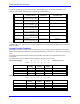
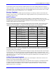

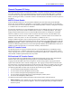
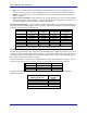
Table Of Contents
- 16-Axis MACRO Slave Station Binding to a MACRO Master
- Mapping Servo Channels to Servo Node
- Mapping Motor Node Registers
- Mapping Motor Function Registers to Node Registers
- Mapping of General Purpose I/O
- UMAC (Pack) Configuration
- I/O Accessory Boards
- Auto Configuration and Identification of UMAC (Pack) Boards
- UMAC (Pack) Interface/Breakout Boards
- MACRO Ring Rules
- I7: Phase Cycle Extension
- I19: Clock Source I-Variable Number
- Turbo PMAC2 Ultralite: I6800 and I6801
- UMAC Turbo
- Notes on Servo Clock
- I6840: MACRO IC 0 Master Configuration
- I6890/I6940/I6990: MACRO IC 1/2/3 Master Configuration
- I6841/I6891/I6941/I6991: MACRO IC 0/1/2/3 Node Activation Control
- I70/I72/I74/I76: MACRO IC 0/1/2/3 Node Auxiliary Function Enable
- I71/I73/I75/I77: MACRO IC 0/1/2/3 Node Protocol Type Control
- I78: MACRO Master/Slave Auxiliary Communications Timeout
- I79: MACRO Master/Master Auxiliary Communications Timeout
- I80, I81, I82: MACRO Ring Check Period and Limits
- Ixx01: Commutation Enable
- Ixx02: Command Output Address
- Ixx03, Ixx04: Feedback Address
- Ixx10, Ixx95: Absolute Position Address and Format
- Ixx25, Ixx24: Flag Address and Mode
- Ixx70, Ixx71: Commutation Cycle Size
- Ixx75: Absolute Phase Position Offset
- Ixx81, Ixx91: Power-On Phase Position Address and Mode
- Ixx82: Current Loop Feedback Address
- Ixx83: Commutation Feedback Address
- Ring Update Frequency
- Station Servo Clock Frequency
- MACRO IC 0
- MACRO IC 1
- MACRO IC 0
- MACRO IC 1
- Channels 1-4 (First 4-Axis Board)
- Channels 5-8 (Second 4-Axis Board)
- On Board Auxiliary Channels (Handwheel/Pulse and Direction)
- Incremental Digital Encoder Feedback
- Analog Encoder Feedback
- Resolver Feedback
- MLDT Feedback
- 12-Bit A/D Converter Feedback
- 14E Parallel Feedback
- MI17 Amplifier Fault Disable Control
- MI18 Amplifier Fault Polarity Control
- MI10x Position Feedback Address
- MI11x Power-On Position Feedback Address
- MI16x Power-On MLDT Excitation Value
- MI975 I/O Node Enable
- MI19 I/O Transfer Period
- Bi-Directional I/O Transfer Control
- Uni-Directional I/O Transfer Control
- Setting the Trigger Condition
- Using for Homing
- Using in User Program
- Setting up for a Single Pulse Output
- Setting up for Multiple Pulse Outputs
- How to Enable and Disable MACRO ASCII Communication Mode
- The Ring Order Method
- Example: Read Using MM-Variables – Actual Encoder
- Example: Read DAC Output from Servo IC Card
- Example: Monitor Up/Down Counter from Servo IC Card
- Example: Write to DACnB on Servo IC Card
- Example: Read Using MI198 and MI199 – Direct Hal
- Example: Read Using MI198 and MI199 – Actual DAC

16-Axis MACRO CPU User Manual
16-Axis MACRO CPU Software Setup 43
The following table shows the conversion table MI-Variable values for this type of feedback with
channels in the UMAC MACRO pack configuration for MACRO IC 1:
Encoder # Which Backplane
Axis Board Used
Location
On Board
Conversion Table MI-
Variable Value
Encoder 1 Acc-24E2x
S1-1,3,4 = ON, OFF, ON
First channel $009000
Encoder 2 Acc-24E2x
S1-1,3,4 = ON, OFF, ON
Second channel $009008
Encoder 3 Acc-24E2x
S1-1,3,4 = ON, OFF, ON
Third channel $009010
Encoder 4 Acc-24E2x
S1-1,3,4 = ON, OFF, ON
Fourth channel $009018
Encoder 5 Acc-24E2x
S1-1,3,4 = OFF, OFF, ON
First channel $009040
Encoder 6 Acc-24E2x
S1-1,3,4 = OFF, OFF, ON
Second channel $009048
Encoder 7 Acc-24E2x
S1-1,3,4 = OFF, OFF, ON
Third channel $009050
Encoder 8 Acc-24E2x
S1-1,3,4 = OFF, OFF, ON
Fourth channel $009058
If not using the 1/T extension of the encoder value, the first hex digit of the MI-Variable value should be
changed from 0 to C. This setting is recommended when using the simulated feedback from a pulse-and-
direction output.
Analog Encoder Feedback
If an analog sine-wave encoder is processed through an Acc-51E high-resolution backplane interpolator
board, the $F0 conversion method is used yielding 4096 states per encoder line. This entry is a three-line
entry.
The following table describes the three-line MI-Variables that need to be configured for the Ubus
Interpolator.
The tables below show the addresses of the quadrature register in the Acc-51E:
Interp SW1 Settings: 6 5 4 3 2 1 UMAC Servo IC 1
1
st
Intrp on on on on on on
I-Variables First Line
Setting
Second Line
Setting
Third Line
Setting
Meaning
MI120,MI121,MI122 $F08000 $8005 $00 Acc-51E Encoder Ch 1
MI123,MI124,MI125 $F08008 $800D $00 Acc-51E Encoder Ch 2
MI126,MI127,MI128 $F08010 $8015 $00 Acc-51E Encoder Ch 3
MI129,MI130,MI131 $F08018 $801D $00 Acc-51E Encoder Ch 4
Interp SW1 Settings: 6 5 4 3 2 1 UMAC Servo IC 2
1
st
Intrp on on on on on off
I- Variables First Line
Setting
Second Line
Setting
Third Line
Setting
Meaning
MI132,MI133,MI134 $F08040 $8045 $00 Acc-51E Encoder Ch 1
MI135,MI136,MI137 $F08048 $804D $00 Acc-51E Encoder Ch 2
MI138,MI139,MI140 $F08050 $8055 $00 Acc-51E Encoder Ch 3
MI141,MI142,MI143 $F08058 $805D $00 Acc-51E Encoder Ch 4