
User's Manual
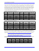

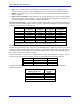
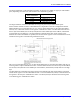
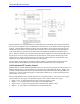
Table Of Contents
- 16-Axis MACRO Slave Station Binding to a MACRO Master
- Mapping Servo Channels to Servo Node
- Mapping Motor Node Registers
- Mapping Motor Function Registers to Node Registers
- Mapping of General Purpose I/O
- UMAC (Pack) Configuration
- I/O Accessory Boards
- Auto Configuration and Identification of UMAC (Pack) Boards
- UMAC (Pack) Interface/Breakout Boards
- MACRO Ring Rules
- I7: Phase Cycle Extension
- I19: Clock Source I-Variable Number
- Turbo PMAC2 Ultralite: I6800 and I6801
- UMAC Turbo
- Notes on Servo Clock
- I6840: MACRO IC 0 Master Configuration
- I6890/I6940/I6990: MACRO IC 1/2/3 Master Configuration
- I6841/I6891/I6941/I6991: MACRO IC 0/1/2/3 Node Activation Control
- I70/I72/I74/I76: MACRO IC 0/1/2/3 Node Auxiliary Function Enable
- I71/I73/I75/I77: MACRO IC 0/1/2/3 Node Protocol Type Control
- I78: MACRO Master/Slave Auxiliary Communications Timeout
- I79: MACRO Master/Master Auxiliary Communications Timeout
- I80, I81, I82: MACRO Ring Check Period and Limits
- Ixx01: Commutation Enable
- Ixx02: Command Output Address
- Ixx03, Ixx04: Feedback Address
- Ixx10, Ixx95: Absolute Position Address and Format
- Ixx25, Ixx24: Flag Address and Mode
- Ixx70, Ixx71: Commutation Cycle Size
- Ixx75: Absolute Phase Position Offset
- Ixx81, Ixx91: Power-On Phase Position Address and Mode
- Ixx82: Current Loop Feedback Address
- Ixx83: Commutation Feedback Address
- Ring Update Frequency
- Station Servo Clock Frequency
- MACRO IC 0
- MACRO IC 1
- MACRO IC 0
- MACRO IC 1
- Channels 1-4 (First 4-Axis Board)
- Channels 5-8 (Second 4-Axis Board)
- On Board Auxiliary Channels (Handwheel/Pulse and Direction)
- Incremental Digital Encoder Feedback
- Analog Encoder Feedback
- Resolver Feedback
- MLDT Feedback
- 12-Bit A/D Converter Feedback
- 14E Parallel Feedback
- MI17 Amplifier Fault Disable Control
- MI18 Amplifier Fault Polarity Control
- MI10x Position Feedback Address
- MI11x Power-On Position Feedback Address
- MI16x Power-On MLDT Excitation Value
- MI975 I/O Node Enable
- MI19 I/O Transfer Period
- Bi-Directional I/O Transfer Control
- Uni-Directional I/O Transfer Control
- Setting the Trigger Condition
- Using for Homing
- Using in User Program
- Setting up for a Single Pulse Output
- Setting up for Multiple Pulse Outputs
- How to Enable and Disable MACRO ASCII Communication Mode
- The Ring Order Method
- Example: Read Using MM-Variables – Actual Encoder
- Example: Read DAC Output from Servo IC Card
- Example: Monitor Up/Down Counter from Servo IC Card
- Example: Write to DACnB on Servo IC Card
- Example: Read Using MI198 and MI199 – Direct Hal
- Example: Read Using MI198 and MI199 – Actual DAC

16-Axis MACRO CPU User Manual
44 16-Axis MACRO CPU Software Setup
The third line contains a bias term that is added to both A/D converter readings before the arctangent
value is calculated. It is used as a 24-bit value, with the used portion of the A/D converter readings being
in the upper 12 bits. For example, if the cycle’s average reading from the A/D converters were -5 LSBs
of the 12-bit value, this line would be set to +5 x 2
12
, or 20,480.
Resolver Feedback
If a resolver is used for servo feedback processed through an Acc-8D Opt 7 R/D Converter board, the
feedback comes into the 16-Axis MACRO CPU as digital quadrature and is processed the same as a true
incremental digital encoder.
MLDT Feedback
If a magnetostrictive linear displacement transducer (MLDT) is used for feedback with the 16-Axis
MACRO CPU providing the excitation pulse and measuring the time until it receives the echo pulse using
its encoder timer circuitry, then the $30 parallel feedback conversion method is used reading the
encoder’s timer register as the position value.
This conversion method uses three lines (MI-Variables) of the conversion table. The first MI-Variable
contains the method and address. The following table shows the first conversion table MI-Variable
values for this type of feedback with channels in the UMAC MACRO pack configuration:
Encoder # Which Backplane Axis
Board Used*
Location On
Board
Conversion Table
MI-Variable Value
Encoder 1 Acc-24E2x w/
S1-1,3,4 = ON, ON, ON
First channel $308000
Encoder 2 Acc-24E2x w/
S1-1,3,4 = ON, ON, ON
Second channel $308008
Encoder 3 Acc-24E2x w/
S1-1,3,4 = ON, ON, ON
Third channel $308010
Encoder 4 Acc-24E2x w/
S1-1,3,4 = ON, ON, ON
Fourth channel $308018
Encoder 5 Acc-24E2x w/
S1-1,3,4 = OFF, ON, ON
First channel $308040
Encoder 6 Acc-24E2x w/
S1-1,3,4 = OFF, ON, ON
Second channel $308048
Encoder 7 Acc-24E2x w/
S1-1,3,4 = OFF, ON, ON
Third channel $308050
Encoder 8 Acc-24E2x w/
S1-1,3,4 = OFF, ON, ON
Fourth channel $308058
The second line of the entry contains a bits used mask, a 24-bit value that contains a 1 in each bit that is to
be used from the register. In this type of feedback, all 24 bits of the source register can be used, so this
line (MI-Variable) can be $FFFFFF.
The third line of the entry contains the maximum change in the input value that the table will let through
in one ring cycle. This provides a filter that is a protection against missing or added echo pulses. This
value should be set to a value slightly greater than the maximum true velocity expected. The units are bits
of the timer per ring cycle, where one bit of the timer represents 0.0009 inches or 0.024 mm at the 120
MHz timer frequency.
12-Bit A/D Converter Feedback
If an analog input processed through the Acc-36E or Acc-59E backplane A/D boards is used for servo
feedback, then the $20 parallel feedback format is used.
The actual ADC inputs are all read through 16-Axis MACRO CPU I/O register in a multiplexed format.
The Station firmware de-multiplexes them automatically into separate internal memory registers at
Y:$0200 to Y:$0207 for MACRO IC 0 and Y:$208 to Y:$20F for MACRO IC 1 if Station variable
MI987 has been set to 1 for both ICs.