
User's Manual
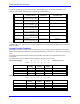
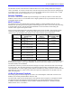
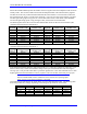

Table Of Contents
- 16-Axis MACRO Slave Station Binding to a MACRO Master
- Mapping Servo Channels to Servo Node
- Mapping Motor Node Registers
- Mapping Motor Function Registers to Node Registers
- Mapping of General Purpose I/O
- UMAC (Pack) Configuration
- I/O Accessory Boards
- Auto Configuration and Identification of UMAC (Pack) Boards
- UMAC (Pack) Interface/Breakout Boards
- MACRO Ring Rules
- I7: Phase Cycle Extension
- I19: Clock Source I-Variable Number
- Turbo PMAC2 Ultralite: I6800 and I6801
- UMAC Turbo
- Notes on Servo Clock
- I6840: MACRO IC 0 Master Configuration
- I6890/I6940/I6990: MACRO IC 1/2/3 Master Configuration
- I6841/I6891/I6941/I6991: MACRO IC 0/1/2/3 Node Activation Control
- I70/I72/I74/I76: MACRO IC 0/1/2/3 Node Auxiliary Function Enable
- I71/I73/I75/I77: MACRO IC 0/1/2/3 Node Protocol Type Control
- I78: MACRO Master/Slave Auxiliary Communications Timeout
- I79: MACRO Master/Master Auxiliary Communications Timeout
- I80, I81, I82: MACRO Ring Check Period and Limits
- Ixx01: Commutation Enable
- Ixx02: Command Output Address
- Ixx03, Ixx04: Feedback Address
- Ixx10, Ixx95: Absolute Position Address and Format
- Ixx25, Ixx24: Flag Address and Mode
- Ixx70, Ixx71: Commutation Cycle Size
- Ixx75: Absolute Phase Position Offset
- Ixx81, Ixx91: Power-On Phase Position Address and Mode
- Ixx82: Current Loop Feedback Address
- Ixx83: Commutation Feedback Address
- Ring Update Frequency
- Station Servo Clock Frequency
- MACRO IC 0
- MACRO IC 1
- MACRO IC 0
- MACRO IC 1
- Channels 1-4 (First 4-Axis Board)
- Channels 5-8 (Second 4-Axis Board)
- On Board Auxiliary Channels (Handwheel/Pulse and Direction)
- Incremental Digital Encoder Feedback
- Analog Encoder Feedback
- Resolver Feedback
- MLDT Feedback
- 12-Bit A/D Converter Feedback
- 14E Parallel Feedback
- MI17 Amplifier Fault Disable Control
- MI18 Amplifier Fault Polarity Control
- MI10x Position Feedback Address
- MI11x Power-On Position Feedback Address
- MI16x Power-On MLDT Excitation Value
- MI975 I/O Node Enable
- MI19 I/O Transfer Period
- Bi-Directional I/O Transfer Control
- Uni-Directional I/O Transfer Control
- Setting the Trigger Condition
- Using for Homing
- Using in User Program
- Setting up for a Single Pulse Output
- Setting up for Multiple Pulse Outputs
- How to Enable and Disable MACRO ASCII Communication Mode
- The Ring Order Method
- Example: Read Using MM-Variables – Actual Encoder
- Example: Read DAC Output from Servo IC Card
- Example: Monitor Up/Down Counter from Servo IC Card
- Example: Write to DACnB on Servo IC Card
- Example: Read Using MI198 and MI199 – Direct Hal
- Example: Read Using MI198 and MI199 – Actual DAC

16-Axis MACRO CPU User Manual
16-Axis MACRO CPU Software Setup 45
Station MI-Variable MI989 specifies the address of the I/O register where the multiplexed A/D converters
actually reside. The conversion table will read the de-multiplexed data in the internal memory registers.
The first line of the entry contains the $20 method and the source address. The second line contains the
bits used mask word, which is a 24-bit value containing a 1 for every bit of the source register to be used.
The first eight analog inputs occupy the low 12 bits of the 24-bit word, so their mask word is $000FFF.
The second eight analog inputs occupy the high 12 bits, so their mask word is $FFF000.
The following table shows the conversion table MI-Variable values for the first and second lines (MI-
variables) of these entries for MACRO IC 0:
Analog
Input Pin
Entry First MI-
Variable Value
Entry Second MI-
Variable Value
Analog
Input Pin
Entry First MI-
Variable Value
Entry Second MI-
Variable Value
ANAI00 $200200 $000FFF ANAI08 $200200 $FFF000
ANAI01 $200201 $000FFF ANAI09 $200201 $FFF000
ANAI02 $200202 $000FFF ANAI10 $200202 $FFF000
ANAI03 $200203 $000FFF ANAI11 $200203 $FFF000
ANAI04 $200204 $000FFF ANAI12 $200204 $FFF000
ANAI05 $200205 $000FFF ANAI13 $200205 $FFF000
ANAI06 $200206 $000FFF ANAI14 $200206 $FFF000
ANAI07 $200207 $000FFF ANAI15 $200207 $FFF000
The following table shows the conversion table MI-variable values for the first and second lines (MI-
variables) of these entries for MACRO IC 1:
Analog
Input Pin
Entry First MI-
Variable Value
Entry Second MI-
Variable Value
Analog
Input Pin
Entry First MI-
Variable Value
Entry Second MI-
Variable Value
ANAI00 $200208 $000FFF ANAI08 $200208 $FFF000
ANAI01 $200209 $000FFF ANAI09 $200209 $FFF000
ANAI02 $20020A $000FFF ANAI10 $20020A $FFF000
ANAI03 $20020B $000FFF ANAI11 $20020B $FFF000
ANAI04 $20020C $000FFF ANAI12 $20020C $FFF000
ANAI05 $20020D $000FFF ANAI13 $20020D $FFF000
ANAI06 $20020E $000FFF ANAI14 $20020E $FFF000
ANAI07 $20020F $000FFF ANAI15 $20020F $FFF000
If the $30 filtered parallel method is used instead of $20, it is a 3-line entry instead of a 2-line entry. The
third line of the entry contains the maximum change in the input value that the table will let through in
one ring cycle. This provides a filter that is a protection against noise. This value should be set to a value
slightly greater than the maximum true velocity expected. The units are bits of the ADC per ring cycle.
Note:
Station Variable MI988 controls whether the A/D converters are expecting inputs
in the -2.5V to +2.5V range or in the 0 to +5V range.
This method can be used also for the 16-bit ADCs on an Acc-28E backplane board. The following table
shows the possible entry settings, depending on the settings of dip switch S1 on the board.
S1-1 S1-2 ADC1 ADC2 ADC3 ADC4
ON ON $18FFE0 $18FFE1 $18FFE2 $18FFE3
OFF ON $18FFE8 $18FFE9 $18FFEA $18FFEB
ON OFF $18FFF0 $18FFF1 $18FFF2 $18FFF3
OFF OFF $18B8C0* $18B8C1* $18B8C2* $18B8C3*
* Requires Station firmware revision V1.115 or newer to use this setting.