
User's Manual
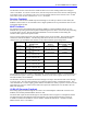
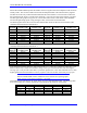

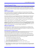
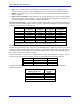
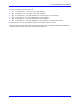
Table Of Contents
- 16-Axis MACRO Slave Station Binding to a MACRO Master
- Mapping Servo Channels to Servo Node
- Mapping Motor Node Registers
- Mapping Motor Function Registers to Node Registers
- Mapping of General Purpose I/O
- UMAC (Pack) Configuration
- I/O Accessory Boards
- Auto Configuration and Identification of UMAC (Pack) Boards
- UMAC (Pack) Interface/Breakout Boards
- MACRO Ring Rules
- I7: Phase Cycle Extension
- I19: Clock Source I-Variable Number
- Turbo PMAC2 Ultralite: I6800 and I6801
- UMAC Turbo
- Notes on Servo Clock
- I6840: MACRO IC 0 Master Configuration
- I6890/I6940/I6990: MACRO IC 1/2/3 Master Configuration
- I6841/I6891/I6941/I6991: MACRO IC 0/1/2/3 Node Activation Control
- I70/I72/I74/I76: MACRO IC 0/1/2/3 Node Auxiliary Function Enable
- I71/I73/I75/I77: MACRO IC 0/1/2/3 Node Protocol Type Control
- I78: MACRO Master/Slave Auxiliary Communications Timeout
- I79: MACRO Master/Master Auxiliary Communications Timeout
- I80, I81, I82: MACRO Ring Check Period and Limits
- Ixx01: Commutation Enable
- Ixx02: Command Output Address
- Ixx03, Ixx04: Feedback Address
- Ixx10, Ixx95: Absolute Position Address and Format
- Ixx25, Ixx24: Flag Address and Mode
- Ixx70, Ixx71: Commutation Cycle Size
- Ixx75: Absolute Phase Position Offset
- Ixx81, Ixx91: Power-On Phase Position Address and Mode
- Ixx82: Current Loop Feedback Address
- Ixx83: Commutation Feedback Address
- Ring Update Frequency
- Station Servo Clock Frequency
- MACRO IC 0
- MACRO IC 1
- MACRO IC 0
- MACRO IC 1
- Channels 1-4 (First 4-Axis Board)
- Channels 5-8 (Second 4-Axis Board)
- On Board Auxiliary Channels (Handwheel/Pulse and Direction)
- Incremental Digital Encoder Feedback
- Analog Encoder Feedback
- Resolver Feedback
- MLDT Feedback
- 12-Bit A/D Converter Feedback
- 14E Parallel Feedback
- MI17 Amplifier Fault Disable Control
- MI18 Amplifier Fault Polarity Control
- MI10x Position Feedback Address
- MI11x Power-On Position Feedback Address
- MI16x Power-On MLDT Excitation Value
- MI975 I/O Node Enable
- MI19 I/O Transfer Period
- Bi-Directional I/O Transfer Control
- Uni-Directional I/O Transfer Control
- Setting the Trigger Condition
- Using for Homing
- Using in User Program
- Setting up for a Single Pulse Output
- Setting up for Multiple Pulse Outputs
- How to Enable and Disable MACRO ASCII Communication Mode
- The Ring Order Method
- Example: Read Using MM-Variables – Actual Encoder
- Example: Read DAC Output from Servo IC Card
- Example: Monitor Up/Down Counter from Servo IC Card
- Example: Write to DACnB on Servo IC Card
- Example: Read Using MI198 and MI199 – Direct Hal
- Example: Read Using MI198 and MI199 – Actual DAC

16-Axis MACRO CPU User Manual
46 16-Axis MACRO CPU Software Setup
To integrate the A/D value before computing the result, the first hex digit of the entry should be changed
from a 1 to a 5. In this case, there is a second line to the entry which specifies a bias value that is
subtracted from the A/D reading before the integration. This bias is expressed as a 24-bit value, with the
upper 16 bits matching the actual data from the A/D converter. For example, if zero voltage into the A/D
converter produced a reading of three LSBs of the converter, the bias term should be set to 3 x 2
8
, or 768.
14E Parallel Feedback
If parallel data brought in through one of the connectors on an Acc-14E I/O backplane board is used for
servo feedback, the $3x conversion method is used for parallel feedback.
Each connector can bring in up to 24 bits of input, mapped as a byte in each of three consecutive words of
memory, with the least significant byte mapped into the low address. The least significant bit of the input
should be connected to the lowest-numbered I/O point on the connector. The J4 and J5 connectors map
into the low byte of these words; the J6 and J7 connectors map into the middle byte; and the J8 and J9
connectors map into the high byte.
If the x digit in the method is 4, the low byte of the three words is used; if x is 5, the middle byte is used;
if x is 6, the high byte is used. The address specified is the low address of the three words used.
The following table shows the conversion table MI-Variable values for the first line of the entry for this
type of feedback through an Acc-14E backplane board:
S1-1 S1-2 Connector Used Entry First MI-Variable Value
ON ON Top $34FFE0
ON ON Bottom $34FFE3
OFF ON Top $34FFE8
OFF ON Bottom $34FFEB
ON OFF Top $34FFF0
ON OFF Bottom $34FFF3
OFF OFF Top $34B8C0*
OFF OFF Bottom $34B8C3*
* Requires Station firmware revision V1.115 or newer to use this setting.
Amplifier Fault Enable and Polarity Control
MI17 and MI18 define whether and how the amplifier-fault inputs to the station are used. Each is an 8-bit
variable with one bit for each servo node. The following table shows which bit matches which servo node:
Node Number ‘n’
0 1 4 5 8 9 12 (C) 13 (D)
MI17, MI18 Bit #
0 1 2 3 4 5 6 7
The matching of servo nodes to hardware channel numbers is determined by the setting of rotary switch SW1.
MI17 Amplifier Fault Disable Control
MI17 disables the display of the amplifier fault inputs. It does not affect the AMP fault being transferred
to the PMAC. Ix25 must be used to disable the PMAC AMP fault bit. If a bit of M117 is set to the
default of 0, the display of the amplifier fault input for the channel connected to that node is enabled. If
the bit is set to 1, the display of the amplifier fault input is disabled.
MI18 Amplifier Fault Polarity Control
MI18 determines the polarity of the amplifier fault inputs. If a bit of MI18 is set to the default of 0, the
amplifier fault input for the channel connected to that node is considered low-true which means that a
logical 0 read on this channel’s fault bit is considered a fault condition, regardless of the input voltage to
create this state. If the bit is set to 1, the amplifier fault input is considered high true which means that a
logical 1 read on this channel’s fault bit is considered a fault condition.