
User's Manual
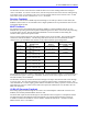

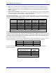
Table Of Contents
- 16-Axis MACRO Slave Station Binding to a MACRO Master
- Mapping Servo Channels to Servo Node
- Mapping Motor Node Registers
- Mapping Motor Function Registers to Node Registers
- Mapping of General Purpose I/O
- UMAC (Pack) Configuration
- I/O Accessory Boards
- Auto Configuration and Identification of UMAC (Pack) Boards
- UMAC (Pack) Interface/Breakout Boards
- MACRO Ring Rules
- I7: Phase Cycle Extension
- I19: Clock Source I-Variable Number
- Turbo PMAC2 Ultralite: I6800 and I6801
- UMAC Turbo
- Notes on Servo Clock
- I6840: MACRO IC 0 Master Configuration
- I6890/I6940/I6990: MACRO IC 1/2/3 Master Configuration
- I6841/I6891/I6941/I6991: MACRO IC 0/1/2/3 Node Activation Control
- I70/I72/I74/I76: MACRO IC 0/1/2/3 Node Auxiliary Function Enable
- I71/I73/I75/I77: MACRO IC 0/1/2/3 Node Protocol Type Control
- I78: MACRO Master/Slave Auxiliary Communications Timeout
- I79: MACRO Master/Master Auxiliary Communications Timeout
- I80, I81, I82: MACRO Ring Check Period and Limits
- Ixx01: Commutation Enable
- Ixx02: Command Output Address
- Ixx03, Ixx04: Feedback Address
- Ixx10, Ixx95: Absolute Position Address and Format
- Ixx25, Ixx24: Flag Address and Mode
- Ixx70, Ixx71: Commutation Cycle Size
- Ixx75: Absolute Phase Position Offset
- Ixx81, Ixx91: Power-On Phase Position Address and Mode
- Ixx82: Current Loop Feedback Address
- Ixx83: Commutation Feedback Address
- Ring Update Frequency
- Station Servo Clock Frequency
- MACRO IC 0
- MACRO IC 1
- MACRO IC 0
- MACRO IC 1
- Channels 1-4 (First 4-Axis Board)
- Channels 5-8 (Second 4-Axis Board)
- On Board Auxiliary Channels (Handwheel/Pulse and Direction)
- Incremental Digital Encoder Feedback
- Analog Encoder Feedback
- Resolver Feedback
- MLDT Feedback
- 12-Bit A/D Converter Feedback
- 14E Parallel Feedback
- MI17 Amplifier Fault Disable Control
- MI18 Amplifier Fault Polarity Control
- MI10x Position Feedback Address
- MI11x Power-On Position Feedback Address
- MI16x Power-On MLDT Excitation Value
- MI975 I/O Node Enable
- MI19 I/O Transfer Period
- Bi-Directional I/O Transfer Control
- Uni-Directional I/O Transfer Control
- Setting the Trigger Condition
- Using for Homing
- Using in User Program
- Setting up for a Single Pulse Output
- Setting up for Multiple Pulse Outputs
- How to Enable and Disable MACRO ASCII Communication Mode
- The Ring Order Method
- Example: Read Using MM-Variables – Actual Encoder
- Example: Read DAC Output from Servo IC Card
- Example: Monitor Up/Down Counter from Servo IC Card
- Example: Write to DACnB on Servo IC Card
- Example: Read Using MI198 and MI199 – Direct Hal
- Example: Read Using MI198 and MI199 – Actual DAC

16-Axis MACRO CPU User Manual
48 16-Axis MACRO CPU Software Setup
General-Purpose I/O Setup
The general-purpose I/O (that is not associated directly with a motor channel) on the 16-Axis MACRO
CPU can be set up with just a few Station MI-Variables. The basic concept for real-time general-purpose
I/O is that of automatic copying of data between the I/O registers and I/O MACRO nodes. Combined
with the automatic copying of data between MACRO nodes on the Station and MACRO nodes on the
PMAC controlling the Station, an automatic transfer is obtained between the PMAC and the I/O points on
the Station.
MI975 I/O Node Enable
If the I/O MACRO nodes have not already been enabled as part of the initial setup of the MACRO
Station, they can be enabled now with MI975. If switch SW1 on the Station has been set to enable any
motor nodes, there are no active MACRO I/O nodes enabled by default. However, setting Bit n of MI975
to 1 enables Node n for I/O transfer over MACRO.
If switch SW1 has been set to E (14) and MI975 has been set to its default value of 0 at the most recent
power-up/reset, then no motor nodes are enabled, but I/O Node 11 is enabled by default. This setting
simply permits communications to an I/O-only MACRO Station before its configuration is finalized.
However, if MI975 is set to a non-zero value on a Station with SW1 set at E (14), then MI975 alone
controls which I/O nodes are active. Setting Bit n of MI975 to 1 activates Node n for I/O transfer over
MACRO. In this case, Node 11 is not active unless Bit 11 of MI975 is set to 1.
Changes in MI975 take place only at a Station power-up/reset. Therefore, to change which I/O nodes on
a Station are active, MI975 must be changed, the new value stored to non-volatile flash memory with the
MSSAVE{anynode} command, then the board reset (usually with the MS$$${anynode} command).
Note that in determining the final active-node word reported in MI996, the MACRO Station clears bit 15
of MI975 to make sure that node 15 is reserved for auxiliary communications.
MI19 I/O Transfer Period
The general-purpose I/O copying or transfer functions on the MACRO Station are enabled by setting
MI19 greater than zero. If MI19 is greater than 0, its value specifies the period of the transfer in phase
cycles. Typically, this is set to 1 so the transfer is performed every phase cycle. If MI19 is set to 0, none
of the transfer variables explained below have any effect.
Bi-Directional I/O Transfer Control
Several MI-Variables on the MACRO Station enable the bi-directional copying of I/O values between
MACRO nodes and configurable input/output registers on MACRO Station I/O boards.
Copying from the MACRO node to the I/O register is used for setting outputs; copying from the I/O
register to the MACRO node is used for reading inputs. The copying is always done in both directions
for all I/O points, even though each I/O point can be used only as an input or an output at any given time.
Only a zero value (output off) should be written to an I/O point that is currently being used as an input.
The following MACRO I/O boards will use these bi-directional copying variables:
• Acc-9E isolated 48-input backplane (UMAC) board
• Acc-10E isolated 48-output backplane (UMAC) board
• Acc-11E isolated 24-input/24-output backplane (UMAC) board
• Acc-12E isolated 24-input/24-high-power-output backplane (UMAC) board
• Acc-14E 48 I/O backplane (UMAC) board
The following Station MI-Variables perform the bi-directional transfers with these boards:
• MI69 and MI70: These variables copy I/O values between 16-bit MACRO node registers (Registers
1, 2, and 3) and accessory-board I/O registers. These are valuable particularly for single I/O boards
with 48 I/O points.