
User's Manual
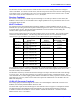
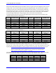

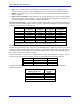
Table Of Contents
- 16-Axis MACRO Slave Station Binding to a MACRO Master
- Mapping Servo Channels to Servo Node
- Mapping Motor Node Registers
- Mapping Motor Function Registers to Node Registers
- Mapping of General Purpose I/O
- UMAC (Pack) Configuration
- I/O Accessory Boards
- Auto Configuration and Identification of UMAC (Pack) Boards
- UMAC (Pack) Interface/Breakout Boards
- MACRO Ring Rules
- I7: Phase Cycle Extension
- I19: Clock Source I-Variable Number
- Turbo PMAC2 Ultralite: I6800 and I6801
- UMAC Turbo
- Notes on Servo Clock
- I6840: MACRO IC 0 Master Configuration
- I6890/I6940/I6990: MACRO IC 1/2/3 Master Configuration
- I6841/I6891/I6941/I6991: MACRO IC 0/1/2/3 Node Activation Control
- I70/I72/I74/I76: MACRO IC 0/1/2/3 Node Auxiliary Function Enable
- I71/I73/I75/I77: MACRO IC 0/1/2/3 Node Protocol Type Control
- I78: MACRO Master/Slave Auxiliary Communications Timeout
- I79: MACRO Master/Master Auxiliary Communications Timeout
- I80, I81, I82: MACRO Ring Check Period and Limits
- Ixx01: Commutation Enable
- Ixx02: Command Output Address
- Ixx03, Ixx04: Feedback Address
- Ixx10, Ixx95: Absolute Position Address and Format
- Ixx25, Ixx24: Flag Address and Mode
- Ixx70, Ixx71: Commutation Cycle Size
- Ixx75: Absolute Phase Position Offset
- Ixx81, Ixx91: Power-On Phase Position Address and Mode
- Ixx82: Current Loop Feedback Address
- Ixx83: Commutation Feedback Address
- Ring Update Frequency
- Station Servo Clock Frequency
- MACRO IC 0
- MACRO IC 1
- MACRO IC 0
- MACRO IC 1
- Channels 1-4 (First 4-Axis Board)
- Channels 5-8 (Second 4-Axis Board)
- On Board Auxiliary Channels (Handwheel/Pulse and Direction)
- Incremental Digital Encoder Feedback
- Analog Encoder Feedback
- Resolver Feedback
- MLDT Feedback
- 12-Bit A/D Converter Feedback
- 14E Parallel Feedback
- MI17 Amplifier Fault Disable Control
- MI18 Amplifier Fault Polarity Control
- MI10x Position Feedback Address
- MI11x Power-On Position Feedback Address
- MI16x Power-On MLDT Excitation Value
- MI975 I/O Node Enable
- MI19 I/O Transfer Period
- Bi-Directional I/O Transfer Control
- Uni-Directional I/O Transfer Control
- Setting the Trigger Condition
- Using for Homing
- Using in User Program
- Setting up for a Single Pulse Output
- Setting up for Multiple Pulse Outputs
- How to Enable and Disable MACRO ASCII Communication Mode
- The Ring Order Method
- Example: Read Using MM-Variables – Actual Encoder
- Example: Read DAC Output from Servo IC Card
- Example: Monitor Up/Down Counter from Servo IC Card
- Example: Write to DACnB on Servo IC Card
- Example: Read Using MI198 and MI199 – Direct Hal
- Example: Read Using MI198 and MI199 – Actual DAC

16-Axis MACRO CPU User Manual
16-Axis MACRO CPU Software Setup 51
MI169 and MI170 can copy data between two 48-bit IOGATE ICs (although only using the first half of
the second IC) and the full 72 bits of a MACRO I/O node (the three 16-bit registers and the single 24-bit
register). The first IOGATE must be in the low byte of the address, the second (if used) must be in the
middle byte of this address. The first IOGATE is matched to the 3 16-bit registers in the MACRO I/O
node whose address is specified, and the half of the second IOGATE is matched to the 24-bit register.
MI171, MI172, and MI173 can copy data between three 48-bit IOGATE ICs at the same base address and
the full 72 bits of two consecutive MACRO I/O nodes (the three 16-bit registers and the single 24-bit
register of each). The first IOGATE must be in the low byte of the address, the second must be in the
middle byte of this address, and the third must be in the high byte.
For more details and examples on the setting of these variables, consult the UMAC MACRO and the
MACRO Stack Software Reference manuals and the individual manuals for the I/O accessories.
Uni-Directional I/O Transfer Control
MACRO Station variables MI21 through MI68 specify uni-directional copying functions between pairs of
MACRO Station registers, usually some kind of I/O register and a MACRO node register. MI20 is a 48-
bit mask variable that specifies which of the 48 possible transfers specified by MI21 through MI68 will
actually occur. MI19 controls the frequency at which these transfers occur; it must be greater than 0 for
these transfers to occur at all.
MI21 through MI68 are 48-bit variables expressed as 12 hexadecimal digits. Each controls one copying
operation from a source register to a destination register. Each variable consists of four parts:
1. Digits 1 and 2: A code representing what part of the source register is used
2. Digits 3 – 6: The address of the source register in the MACRO Station
3. Digits 7 and 8: A code representing what part of the destination register is used
4. Digits 9 – 12: The address of the destination in the MACRO Station