
User's Manual


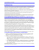
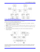
Table Of Contents
- 16-Axis MACRO Slave Station Binding to a MACRO Master
- Mapping Servo Channels to Servo Node
- Mapping Motor Node Registers
- Mapping Motor Function Registers to Node Registers
- Mapping of General Purpose I/O
- UMAC (Pack) Configuration
- I/O Accessory Boards
- Auto Configuration and Identification of UMAC (Pack) Boards
- UMAC (Pack) Interface/Breakout Boards
- MACRO Ring Rules
- I7: Phase Cycle Extension
- I19: Clock Source I-Variable Number
- Turbo PMAC2 Ultralite: I6800 and I6801
- UMAC Turbo
- Notes on Servo Clock
- I6840: MACRO IC 0 Master Configuration
- I6890/I6940/I6990: MACRO IC 1/2/3 Master Configuration
- I6841/I6891/I6941/I6991: MACRO IC 0/1/2/3 Node Activation Control
- I70/I72/I74/I76: MACRO IC 0/1/2/3 Node Auxiliary Function Enable
- I71/I73/I75/I77: MACRO IC 0/1/2/3 Node Protocol Type Control
- I78: MACRO Master/Slave Auxiliary Communications Timeout
- I79: MACRO Master/Master Auxiliary Communications Timeout
- I80, I81, I82: MACRO Ring Check Period and Limits
- Ixx01: Commutation Enable
- Ixx02: Command Output Address
- Ixx03, Ixx04: Feedback Address
- Ixx10, Ixx95: Absolute Position Address and Format
- Ixx25, Ixx24: Flag Address and Mode
- Ixx70, Ixx71: Commutation Cycle Size
- Ixx75: Absolute Phase Position Offset
- Ixx81, Ixx91: Power-On Phase Position Address and Mode
- Ixx82: Current Loop Feedback Address
- Ixx83: Commutation Feedback Address
- Ring Update Frequency
- Station Servo Clock Frequency
- MACRO IC 0
- MACRO IC 1
- MACRO IC 0
- MACRO IC 1
- Channels 1-4 (First 4-Axis Board)
- Channels 5-8 (Second 4-Axis Board)
- On Board Auxiliary Channels (Handwheel/Pulse and Direction)
- Incremental Digital Encoder Feedback
- Analog Encoder Feedback
- Resolver Feedback
- MLDT Feedback
- 12-Bit A/D Converter Feedback
- 14E Parallel Feedback
- MI17 Amplifier Fault Disable Control
- MI18 Amplifier Fault Polarity Control
- MI10x Position Feedback Address
- MI11x Power-On Position Feedback Address
- MI16x Power-On MLDT Excitation Value
- MI975 I/O Node Enable
- MI19 I/O Transfer Period
- Bi-Directional I/O Transfer Control
- Uni-Directional I/O Transfer Control
- Setting the Trigger Condition
- Using for Homing
- Using in User Program
- Setting up for a Single Pulse Output
- Setting up for Multiple Pulse Outputs
- How to Enable and Disable MACRO ASCII Communication Mode
- The Ring Order Method
- Example: Read Using MM-Variables – Actual Encoder
- Example: Read DAC Output from Servo IC Card
- Example: Monitor Up/Down Counter from Servo IC Card
- Example: Write to DACnB on Servo IC Card
- Example: Read Using MI198 and MI199 – Direct Hal
- Example: Read Using MI198 and MI199 – Actual DAC

16-Axis MACRO CPU User Manual
ii Table of Contents
Ring Control Setup Variables..................................................................................................................................32
Ring Update Frequency......................................................................................................................................32
Station Servo Clock Frequency...........................................................................................................................33
Additional Node Enabling and Disabling................................................................................................................33
MACRO IC 0 ......................................................................................................................................................33
MACRO IC 1 ......................................................................................................................................................34
Auto-Detecting the MACRO and Servo ICs ...........................................................................................................34
Binding the Servo ICs to the MACRO ICs .............................................................................................................35
Mapping Machine Interface Channels to MACRO Servo Nodes............................................................................35
MACRO IC 0 ......................................................................................................................................................35
MACRO IC 1 ......................................................................................................................................................36
Multi-Channel Servo Interface Setup......................................................................................................................37
Channels 1-4 (First 4-Axis Board) .....................................................................................................................37
Channels 5-8 (Second 4-Axis Board)..................................................................................................................38
On Board Auxiliary Channels (Handwheel/Pulse and Direction)......................................................................39
Single-Channel Servo Interface Channel Setup ......................................................................................................40
Station Encoder Conversion Table Setup................................................................................................................41
Incremental Digital Encoder Feedback..............................................................................................................42
Analog Encoder Feedback..................................................................................................................................43
Resolver Feedback..............................................................................................................................................44
MLDT Feedback .................................................................................................................................................44
12-Bit A/D Converter Feedback .........................................................................................................................44
14E Parallel Feedback .......................................................................................................................................46
Amplifier Fault Enable and Polarity Control ..........................................................................................................46
MI17 Amplifier Fault Disable Control ...............................................................................................................46
MI18 Amplifier Fault Polarity Control...............................................................................................................46
Servo Address Variable Setup.................................................................................................................................47
MI10x Position Feedback Address .....................................................................................................................47
MI11x Power-On Position Feedback Address....................................................................................................47
MI16x Power-On MLDT Excitation Value .........................................................................................................47
General-Purpose I/O Setup......................................................................................................................................48
MI975 I/O Node Enable......................................................................................................................................48
MI19 I/O Transfer Period...................................................................................................................................48
Bi-Directional I/O Transfer Control...................................................................................................................48
Uni-Directional I/O Transfer Control ................................................................................................................51
HOW TO USE THE 16-AXIS MACRO CPU.........................................................................................................53
Example Setup for 16-Axis System ........................................................................................................................53
Macro Station Position Capture Setup ....................................................................................................................53
Setting the Trigger Condition .............................................................................................................................54
Using for Homing ...............................................................................................................................................54
Using in User Program ......................................................................................................................................54
MACRO Station Position Compare Output Setup ..................................................................................................54
Setting up for a Single Pulse Output...................................................................................................................55
Setting up for Multiple Pulse Outputs.................................................................................................................55
Using the JHW Port Encoder Inputs .......................................................................................................................56
Using the JHW Pulse and Direction Outputs ..........................................................................................................56
Using the JDISP Port...............................................................................................................................................57
MACRO ASCII Communication Mode..................................................................................................................58
How to Enable and Disable MACRO ASCII Communication Mode ..................................................................58
The Ring Order Method......................................................................................................................................59
Using MM-Variables to Verify MACRO Station Memory Locations ....................................................................59
Example: Read Using MM-Variables – Actual Encoder Read from Gate Array................................................59
Data Transfer Examples (MI20-MI68)....................................................................................................................59
Example: Read DAC Output from Servo IC Card .............................................................................................60
Example: Monitor Up/Down Counter from Servo IC Card................................................................................60