
User's Manual
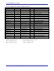
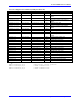


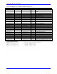

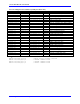
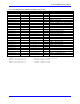
Table Of Contents
- 16-Axis MACRO Slave Station Binding to a MACRO Master
- Mapping Servo Channels to Servo Node
- Mapping Motor Node Registers
- Mapping Motor Function Registers to Node Registers
- Mapping of General Purpose I/O
- UMAC (Pack) Configuration
- I/O Accessory Boards
- Auto Configuration and Identification of UMAC (Pack) Boards
- UMAC (Pack) Interface/Breakout Boards
- MACRO Ring Rules
- I7: Phase Cycle Extension
- I19: Clock Source I-Variable Number
- Turbo PMAC2 Ultralite: I6800 and I6801
- UMAC Turbo
- Notes on Servo Clock
- I6840: MACRO IC 0 Master Configuration
- I6890/I6940/I6990: MACRO IC 1/2/3 Master Configuration
- I6841/I6891/I6941/I6991: MACRO IC 0/1/2/3 Node Activation Control
- I70/I72/I74/I76: MACRO IC 0/1/2/3 Node Auxiliary Function Enable
- I71/I73/I75/I77: MACRO IC 0/1/2/3 Node Protocol Type Control
- I78: MACRO Master/Slave Auxiliary Communications Timeout
- I79: MACRO Master/Master Auxiliary Communications Timeout
- I80, I81, I82: MACRO Ring Check Period and Limits
- Ixx01: Commutation Enable
- Ixx02: Command Output Address
- Ixx03, Ixx04: Feedback Address
- Ixx10, Ixx95: Absolute Position Address and Format
- Ixx25, Ixx24: Flag Address and Mode
- Ixx70, Ixx71: Commutation Cycle Size
- Ixx75: Absolute Phase Position Offset
- Ixx81, Ixx91: Power-On Phase Position Address and Mode
- Ixx82: Current Loop Feedback Address
- Ixx83: Commutation Feedback Address
- Ring Update Frequency
- Station Servo Clock Frequency
- MACRO IC 0
- MACRO IC 1
- MACRO IC 0
- MACRO IC 1
- Channels 1-4 (First 4-Axis Board)
- Channels 5-8 (Second 4-Axis Board)
- On Board Auxiliary Channels (Handwheel/Pulse and Direction)
- Incremental Digital Encoder Feedback
- Analog Encoder Feedback
- Resolver Feedback
- MLDT Feedback
- 12-Bit A/D Converter Feedback
- 14E Parallel Feedback
- MI17 Amplifier Fault Disable Control
- MI18 Amplifier Fault Polarity Control
- MI10x Position Feedback Address
- MI11x Power-On Position Feedback Address
- MI16x Power-On MLDT Excitation Value
- MI975 I/O Node Enable
- MI19 I/O Transfer Period
- Bi-Directional I/O Transfer Control
- Uni-Directional I/O Transfer Control
- Setting the Trigger Condition
- Using for Homing
- Using in User Program
- Setting up for a Single Pulse Output
- Setting up for Multiple Pulse Outputs
- How to Enable and Disable MACRO ASCII Communication Mode
- The Ring Order Method
- Example: Read Using MM-Variables – Actual Encoder
- Example: Read DAC Output from Servo IC Card
- Example: Monitor Up/Down Counter from Servo IC Card
- Example: Write to DACnB on Servo IC Card
- Example: Read Using MI198 and MI199 – Direct Hal
- Example: Read Using MI198 and MI199 – Actual DAC

16-Axis MACRO CPU User Manual
MACRO Equivalent Servo IC Memory Locations 75
Servo IC 4 Registers for Channel 1 (usually for Motor #9)
MACRO Location MIVariable Turbo Location M-Var Description
X:$9001,0,24,S - - M901
ENC9 24-bit counter position
Y:$9002,8,16,S - - M902
OUT9A command value; DAC or PWM
X:$9003,0,24,S MS16,MI921 - M903
ENC9 captured position
Y:$9003,8,16,S - - M904
OUT9B command value; DAC or PWM
Y:$9005,8,16,s MS16,MI922 Y:$79421,8,16,s M905
ADC9A input value
Y:$9006,8,16,s MS16,MI924 Y:$79422,8,16,s M906
ADC9B input value
Y:$9004,8,16,s - - M907
OUT9C command value; PFM or PWM
Y:$9007,0,24,s MS16,MI925 - M908
ENC9 compare A position
X:$9007,0,24,s MS16,MI926 - M909
ENC9 compare B position
X:$9006,0,24,s MS16,MI923 - M910
ENC9 compare auto-increment value
X:$9005,11 MS16,MI928 - M911
ENC9 compare initial state write enable
X:$9005,12 MS16,MI929 - M912
ENC9 compare initial state
X:$9005,14 - Y:$003450,14 M914
AENA9 output status
X:$9000,19 - Y:$003450,19 M915
USER9 flag input status
X:$9000,9 - Y:$003450,9 M916
ENC9 compare output value
X:$9000,11 - Y:$003450,11 M917
ENC9 capture flag
X:$9000,8 - Y:$003450,8 M918
ENC9 count error flag
X:$9000,14 - - M919
CHC9 input status
X:$9000,16 - Y:$003450,16 M920
HMFL9 flag input status
X:$9000,17 - Y:$003450,17 M921
PLIM9 flag input status
X:$9000,18 - Y:$003450,18 M922
MLIM9 flag input status
X:$9000,15 - Y:$003450,15 M923
FAULT9 flag input status
X:$9000,20 - Y:$003450,20 M924
Channel 9 W flag input status
X:$9000,21 - Y:$003450,21 M925
Channel 9 V flag input status
X:$9000,22 - Y:$003450,22 M926
Channel 9 U flag input status
X:$9000,23 - Y:$003450,23 M927
Channel 9 T flag input status
X:$9000,20,4 - Y:$003450,20,4 M928
Channel 9 TUVW inputs as 4-bit value
Suggested MM-Variables:
MM90->X:$9001,0,24,s ; ENC9 24-bit counter position
MM91->Y:$9002,8,16,s ; OUT9A command value
MM92->Y:$9003,8,16,s ; OUT9B command value
MM93->Y:$9004,8,16,s ; OUT9C command value