
User's Manual


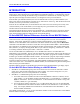
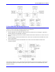
Table Of Contents
- 16-Axis MACRO Slave Station Binding to a MACRO Master
- Mapping Servo Channels to Servo Node
- Mapping Motor Node Registers
- Mapping Motor Function Registers to Node Registers
- Mapping of General Purpose I/O
- UMAC (Pack) Configuration
- I/O Accessory Boards
- Auto Configuration and Identification of UMAC (Pack) Boards
- UMAC (Pack) Interface/Breakout Boards
- MACRO Ring Rules
- I7: Phase Cycle Extension
- I19: Clock Source I-Variable Number
- Turbo PMAC2 Ultralite: I6800 and I6801
- UMAC Turbo
- Notes on Servo Clock
- I6840: MACRO IC 0 Master Configuration
- I6890/I6940/I6990: MACRO IC 1/2/3 Master Configuration
- I6841/I6891/I6941/I6991: MACRO IC 0/1/2/3 Node Activation Control
- I70/I72/I74/I76: MACRO IC 0/1/2/3 Node Auxiliary Function Enable
- I71/I73/I75/I77: MACRO IC 0/1/2/3 Node Protocol Type Control
- I78: MACRO Master/Slave Auxiliary Communications Timeout
- I79: MACRO Master/Master Auxiliary Communications Timeout
- I80, I81, I82: MACRO Ring Check Period and Limits
- Ixx01: Commutation Enable
- Ixx02: Command Output Address
- Ixx03, Ixx04: Feedback Address
- Ixx10, Ixx95: Absolute Position Address and Format
- Ixx25, Ixx24: Flag Address and Mode
- Ixx70, Ixx71: Commutation Cycle Size
- Ixx75: Absolute Phase Position Offset
- Ixx81, Ixx91: Power-On Phase Position Address and Mode
- Ixx82: Current Loop Feedback Address
- Ixx83: Commutation Feedback Address
- Ring Update Frequency
- Station Servo Clock Frequency
- MACRO IC 0
- MACRO IC 1
- MACRO IC 0
- MACRO IC 1
- Channels 1-4 (First 4-Axis Board)
- Channels 5-8 (Second 4-Axis Board)
- On Board Auxiliary Channels (Handwheel/Pulse and Direction)
- Incremental Digital Encoder Feedback
- Analog Encoder Feedback
- Resolver Feedback
- MLDT Feedback
- 12-Bit A/D Converter Feedback
- 14E Parallel Feedback
- MI17 Amplifier Fault Disable Control
- MI18 Amplifier Fault Polarity Control
- MI10x Position Feedback Address
- MI11x Power-On Position Feedback Address
- MI16x Power-On MLDT Excitation Value
- MI975 I/O Node Enable
- MI19 I/O Transfer Period
- Bi-Directional I/O Transfer Control
- Uni-Directional I/O Transfer Control
- Setting the Trigger Condition
- Using for Homing
- Using in User Program
- Setting up for a Single Pulse Output
- Setting up for Multiple Pulse Outputs
- How to Enable and Disable MACRO ASCII Communication Mode
- The Ring Order Method
- Example: Read Using MM-Variables – Actual Encoder
- Example: Read DAC Output from Servo IC Card
- Example: Monitor Up/Down Counter from Servo IC Card
- Example: Write to DACnB on Servo IC Card
- Example: Read Using MI198 and MI199 – Direct Hal
- Example: Read Using MI198 and MI199 – Actual DAC

16-Axis MACRO CPU User Manual
Introduction 1
INTRODUCTION
The 16-Axis MACRO CPU provides a remote interface for encoders, flags, direct-PWM digital drives,
analog drives, and/or digital I/O for a Turbo PMAC2 with MACRO interface. It communicates with the
Turbo PMAC2 solely through the MACRO ring, but interfaces to standard drives, encoders, flags, and
Opto-22 style I/O through on-board connectors. It is designed to run up to sixteen motors.
With the fiber optic MACRO interface, the 16-Axis MACRO CPU can be up to three kilometers (two
miles) away from the Turbo PMAC2 controller or any other station on the ring. With the RJ-45 electrical
interface, it can be up to 30 meters (100 feet) away.
With the 16-Axis MACRO CPU, the Turbo PMAC2 can control servo axes and I/O just as if they were
connected directly to the Turbo PMAC2, even though they are a great distance away and the only
interface from the Turbo PMAC2 is the MACRO ring.
This manual explains the setup of the 16-Axis MACRO CPU. It should be used in conjunction with the
Hardware Reference manuals for the 3U MACRO CPU 16x board, the 3U-format accessories that are
used, and the Software Reference Manual for the 16x MACRO Station.
16-Axis MACRO Station Differences from the 8-Axis MACRO Station
The new 16-Axis MACRO CPU has two MACRO ICs (0 and 1) and each MACRO IC can support servo
control for two Servo ICs each (eight motors). It can be thought of as two of 3U 8-Axis MACRO
Stations. Each UMAC MACRO IC is bound to separate MACRO Masters. Each MACRO Master
addresses its own MACRO IC Slave and the Servo IC MInn variables on the Ring with the MS<node>
commands. Each MACRO IC and Servo IC has their own setup MI variables MI900 – 969 and MI990 –
999. MACRO IC 0’s MI996 (the ring binding MI variable) is determined by SW1 (Nodes enabled) and
SW2 (Master #) or setup by the Ring Order Who are you? software configuring. MACRO IC 1 defaults
to a binding of Master number equal to SW2+1 and node 11 enabled.
The 16-Axis MACRO CPU (DSP56309) is run at 100 MHz where as the 8-Axis MACRO CPU
(DSP56303) is run at 60 MHz. The new CPU has additional program memory and now has the feature of
running a simplified PLCC program locally in the station. This PLCC program has available 512 PMAC
M and P-type variables called MM and MP variables. With the PLCC program, simple integer arithmetic
and logic can be performed locally in the station. This feature comes standard with PEWINPro.
Another new feature includes Turbo PMAC type I4900 (MI200) variables for determining all UMAC
cards in the UMAC rack. Also added in the MI200 variables, are measurements of phase and background
times for duty-cycle measurements.
Hardware additions include two handwheel input channels and the standard PMAC type display output.
16-Axis MACRO Slave Station Binding to a MACRO Master
1. MACRO IC 0’s MI996 binding setup rules are the same as the 8-Axis station where SW1 enables
certain servo nodes and SW2 determines the master number. For software setup (SW1=14): Use
Ring Order Who Are You? to setup MACRO IC 0’s MI996.
2. MACRO IC 1’s MI996 binding setup rules are the following:
a. For modes where SW1 and SW2 are used to bind a MACRO Slave Station to a Master, use the
value of SW2 +1 to set the Master number and enable node 11,15 in MACRO IC 1’s MI996 on a
$$$*** initialization. Then access MACRO IC 1’s MI-Variables from its Master’s using node
11 (MS27, MI996, etc. type commands).
b. For a mode using software setup (SW1=14): Use Ring Order Who Are You? to setup MACRO
IC 0’s MI996 and then add 1000 to the MInn variables to select MACRO IC 1’s MI variables for
setup. For example, MI996 accesses MACRO IC 0 and MI1996 accesses MACRO IC 1. The
same for MI992 and MI1992.
Once MI996 of MACRO IC 1 is set, its associated MInn variables can be accessed from its Turbo PMAC
MACRO Master with MS type commands.