^1 HARDWARE REFERENCE MANUAL ^2 Quad Amp ^3 4-Axis Digital Amplifier ^4 3Ax-602646-xUxx ^5 September 24, 2003 Single Source Machine Control Power // Flexibility // Ease of Use 21314 Lassen Street Chatsworth, CA 91311 // Tel. (818) 998-2095 Fax. (818) 998-7807 // www.deltatau.
Copyright Information © 2003 Delta Tau Data Systems, Inc. All rights reserved. This document is furnished for the customers of Delta Tau Data Systems, Inc. Other uses are unauthorized without written permission of Delta Tau Data Systems, Inc. Information contained in this manual may be updated from time-to-time due to product improvements, etc., and may not conform in every respect to former issues. To report errors or inconsistencies, call or email: Delta Tau Data Systems, Inc.
Quad Amp Hardware Reference Manual Table of Contents INTRODUCTION .......................................................................................................................................................1 Related Technical Documentation ............................................................................................................................1 Safety Summary .......................................................................................................................
Quad Amp Hardware Reference Manual Jumpers, Potentiometers, Test Points, and LEDs ...............................................................................................21 Grounding ...............................................................................................................................................................25 General .......................................................................................................................................................
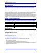
Quad Amp Hardware Reference Manual INTRODUCTION The Delta Tau Data Systems, Inc. 4-axis Digital Amplifier (Quad Amp) is a highly compact digital amplifier and power supply, packaged together to provide four axes of bi-directional (four quadrant) torque control for a variety of AC or DC brushless or AC induction motors. All control parameters including switching frequency and dead time are determined by software set-up of the controller, not in the amplifier.
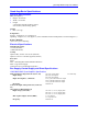
Quad Amp Hardware Reference Manual Quad Amp Basic Specifications Physical Specifications Size (See Figure 1) • Height: 22.0 Inches • Width: 10.5 Inches • Length: 5.125 Inches (without mounting option) 9.031 Inches (with mounting option) Weight • 60 lb. (27.
Quad Amp Hardware Reference Manual Main DC bus Voltage Internal Shunt Resistor Resistance Resistor power External Shunt Resistor (Optional) Resistance Resistor power Soft Start charge time Minimum output inductance 170 VDC (120 VAC line input) (L1, L2) 300 VDC (208 VAC line input) (L1, L2, L3) 325 VDC (230 VAC line input) (L1, L2, L3) For demo only 15 Ohm 1.8 kW 8.5 Ohm 2.
Quad Amp Hardware Reference Manual AIR FLOW USE 1/4-INCH MOUNTING HARDWARE (4 PLACES) Figure 1 Quad Amp Specifications Output Specifications for 120/208/230 VAC Amplifier Up to four blocks (options) can be selected in any power combination. The total power cannot exceed 33 HP. Note: When 30HP is selected only two additional axes may be used (three total instead of four).
Quad Amp Hardware Reference Manual Opt 5 Opt 6 Continuous HP(100%) 0.75 HP 1.5 2 HP 3 HP 5 HP HP 10 HP 15 HP 20 HP 30 Hp 0.56 kW 1.1 kW 1.5 kW 2.2 kW 3.7 kW 5.6 kW 7.5 kW 11 kW 15 kW 22.5 kW Continuous current (RMS) 2A 4A 5A 7A 15 A 20 A 25 A 35 A 50 A 75 A HP Opt 8 Opt 9 Opt 10 Opt 11 Opt 12 Opt 13 Opt 14 7.5 Continuous 2 min HP(200%) 1.5 3 HP 4 HP 6 HP 10 HP 15 HP 20 HP 30 HP 40 HP 60 HP 1.1 kW 2.2 kW 3 kW 4.5 kW 7.
Quad Amp Hardware Reference Manual Protection There are several layers of protection built into the amplifier, including transient voltage filters, transient surge suppressors, fuses, a flyback diode, and a variety of fault detection circuits. These are discussed in the following paragraphs and in the Troubleshooting Chapter.
Quad Amp Hardware Reference Manual Configurable Options Each Quad Amplifier is shipped with an Identification Tag (see Figure 1). The identification tag is attached to the top panel of the Quad Amplifier. It indicates the rating of each axis, the AC operating voltage, and the control input voltage. Since every Quad Amplifier is a custom unit, Delta Tau would like to emphasize that each user should inspect the equipment and see that the correct unit has been supplied.
Quad Amp Hardware Reference Manual Accessories Item Description 3A1-602582-100 3A2-602582-100 200-602739-024 Circuit Breaker Circuit Breaker PWM Input Cables 50 Amps 450 VAC 3 Phase 70 Amps 250 VAC 3 Phase 36” long cable with DB36 pin mini connectors at each end Note With external trip NA Two required per Acc-8F. Connects between Quad Amplifier and Acc-8F 3A0-602757-100 External Shunt Resistor 4.25 Ohms 1400 Watts each. Two required for 208/230 Quad 25” long 2” diameter Edge-Power resistor.
Quad Amp Hardware Reference Manual GETTING STARTED Receiving and Handling Inspection upon Receipt Upon the receipt of equipment, inspect all merchandise for any indication of damage that may have incurred during shipping and handling. If any items are damaged, do not accept them until the freight carrier makes an appropriate notation on the freight bill or express receipt. Claims for loss or damage in shipping must be taken up with the shipping or freight carrier.
Quad Amp Hardware Reference Manual Heat Dissipation The external mounting options (Opt3, Opt3A and Opt3B) allow the Quad Amplifier to be installed inside a cabinet, with the Quad Amplifier heat sink mounted external to the cabinet or in an air plenum. In the case of Opt 3B, provide good air circulation, in a plenum, with a minimum airflow across the heat sink of 70 CFM.
Quad Amp Hardware Reference Manual THEORY OF OPERATION Operation The Quad Amplifier is a universal 4-axis 3-phase direct PWM drive which utilizes the latest in smart power technology from the world’s leading vendors and the cutting edge algorithms of the new PMAC2 controller family. The Quad Amplifier is capable of driving all of the motor types commonly used in programmable motion control in both rotary and linear forms.
Quad Amp Hardware Reference Manual Current Sense Board The Current Sense Board has eight Hall Effect (LEM) modules for current sense and eight on-board A/D converters that transform four channels of motor current to digital form. Each channel provides information on two phases (A phase and B phase). The third phase is mathematically created in the PMAC2.
Quad Amp Hardware Reference Manual Heat Dissipation The capability of the Quad Amplifier and the IGBT modules is based upon the heat they can dissipate; the more quickly heat can be removed from the IGBT module, the more current it can handle. Heat is created whenever an IGBT is turned on or off. These transitions are called switching losses. Whenever current is flowing, the switching losses represent a sizable and unavoidable part of the heat generated by the Quad Amplifier.
Quad Amp Hardware Reference Manual 14 Theory of Operation
Quad Amp Hardware Reference Manual INSTALLATION Wiring the Quad Amplifier System Quad Amplifier Channel Connections The Quad Amplifier channels must be connected in a particular order for proper operation. It is essential that the timing of all signals associated with the Quad Amplifier logic board shares the ADC converter clocks for Quad v channels 1-2 and channels 3-4. The ADC clocks are generated from the gate array associated with the axis channel on the PMAC.
Quad Amp Hardware Reference Manual Non-Standard Quad Amplifier Setup This example shows the Quad Amplifier setup with PMAC axes 1, 2, 7, and 8 are connected to first Quad Amplifier #1 and PMAC Axes 3, 4, 5 and 6 are connected to first Quad Amplifier #2. Since first Quad Amplifier channels 1-2 and 3-4 share ADC clock signals, the PMAC channels connected to these amplifier channels must be generated at the same Gate Array.
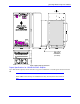
Quad Amp Hardware Reference Manual CHASSIS GROUND BUS- L3 SHUNT L2 L1 BUS+ C1 OPTIONAL EXTERNAL SHUNT 1 C2 1 C3 1 E-STOP/READY EXTERNAL GROUND FAULT TRIP CONTROL AC VOLTAGE TOP VIEW MOTOR CABLES MOTOR GROUNDS AXIS 2 AXIS 1 1 2 3 4 AXIS 1 AXIS 4 AXIS 3 W V U W V U W V U W V U AXIS 3 AXIS 4 AXIS 2 MOTOR OVERTEMP CONNECTOR CONNECT TO ACC-8F BOTTOM VIEW Figure 5 and 6 Quad Amplifier Connector Locations Installation 17
Quad Amp Hardware Reference Manual 18 Pin# Symbol Function 1 2 3 4 5 6 7 8 9 10 11 12 13 14 15 16 17 18 19 20 21 22 23 24 25 26 27 28 29 30 31 32 33 34 35 36 Fc_A1 Fc_C1 Clk0+ Convert0+ Atddaa1+ Atddab1+ Aena1+ Fault1+ Pwmatop1+ Pwmabot1+ Pwmbtop1+ Pwmbbot1+ Pwmctop1+ Pwmcbot1+ Gnd Pmac_+5 NC NC Fc_B1 Fc_D1 Clk0Convert0Atddaa1Atddab1Aena1Fault1Pwmatop1Pwmabot1Pwmbtop1Pwmbbot1Pwmctop1Pwmcbot1Gnd (X)Pmac_+5 NC NC Input Input Input Input Output Output Input Output Input Input Input Input Input Input Com
Quad Amp Hardware Reference Manual Figure 7 Quad Amp Main Circuit Wiring Diagram Main AC Input Power Connect desired main input power to input terminals marked L1, L2, and L3 (see Figure 7). The power ground can be connected at the terminal marked CHAS GND or at the grounding screw, marked E, located on the end panel of the Quad Amplifier chassis. The main input power terminals are rated for 600V and 85 Amps.
Quad Amp Hardware Reference Manual For 460 VAC Operation Jump pin 4 to pin 5. Power is applied to pins 1 and 8 via AC input connector C3. For 480 VAC Operation Jump pin 4 to pin 5 and pin 8 to pin 9. Power is applied to pins 1 and 10 via AC input connector C3.
Quad Amp Hardware Reference Manual Bus Power Enable/Emergency Stop CAUTION: Any wiring should be attempted only after the drive has been isolated from the main AC supply and 10 to 12 minutes has elapsed to allow the internal bus capacitors to discharge. The normally open (NO) Main AC Contactor auxiliary contacts must be wired and connected to Connector C1 pins 1 and 2, otherwise the Quad Amplifier will not power up.
Quad Amp Hardware Reference Manual 312 13 2 Figure 10 Logic I/O Board Jumper and LED Locations Name Position E1-E4 IN OUT IN OUT IN OUT IN OUT IN OUT IN OUT IN OUT IN OUT E7 E8 E9 E10 E28 E29 E30 22 LED Symbol D5 D6 D7 D14 D15 D16 D17 D18 D19 D20 D21 D22 D50 D55 + 15 V +5V - 15 V AXIS 1 FLT AXIS 2 FLT AXIS 3 FLT AXIS 4 FLT AXIS 1 EN AXIS 2 EN AXIS 3 EN AXIS 4 EN PWR GOOD GOT ENABLE VNI Description Default Shield To Local Ground Open Do Not Use Open Enable Shunt Transistor In Module Open
Quad Amp Hardware Reference Manual Figure 11 Current Sense Board Jumper and LED Locations Name Position E1A-E4A IN OUT IN OUT IN OUT IN OUT E1B-E4B E5 E6 LED Symbol D5 D6 D7 +5V + 15 V - 15 V Installation Description Default Enable Serial Fault Data, Phase A Open Enable Serial Fault Data, Phase B Open Clock Polarity 2 and 3 Jumpered Convert Polarity 2 and 3 Jumpered Description On when + 5Vdc logic power is present On when + 15Vdc logic power is present On when - 15Vdc logic power is p
Quad Amp Hardware Reference Manual Figure 62 Soft Start Board Jumper, Potentiometer, Test Point, and LED Locations Name Position E1 1-2 jumper 2-3 open Jumper Jumper JP6 JP7 Description Default Internal Power Supply Connection E-Stop Configuration E-Stop Configuration Symbol` Description Tp Factory Set R4 & TP5 R2 & TP4 TP3 High line fault set point Over voltage fault set point Shunt IGBT turn-on set point 5.2/10.4 V 4.1/8.2 V 3.7V @ 230 VAC TP2 Main IGBT turn-on set point 2.
Quad Amp Hardware Reference Manual Grounding General It is important to follow some precautions to avoid ground loops or unwanted electrical noise disturbances. • All signal cables must be shielded. • Two or more power wires in the same sleeve must be twisted and shielded. • A shield that does not carry current can be connected at both ends • A cable with low power electrical signals should never run in the same proximity of high power cables.
Quad Amp Hardware Reference Manual Note: The Quad Amplifier has a built-in protection against accidentally setting I900 (PWM frequency) too high, and exceeding the PWM input frequency rating of the power blocks. I9n6 For machine interface channel n, I9n6 must be set to 0 to select PWM output format. If i9n6 is set to 1 or 3 while a ‘n’ axis is enabled, Quad Amplifier will disable all enabled axes and the LED display will show code ‘A’.
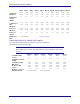
Quad Amp Hardware Reference Manual During this tuning process, P2Setup also determines the commutation parameters and commands the PMAC appropriately. Power Block Option Continuous Hp 5 6 7 8 9 10 11 12 13 14 0.75 1.5 2 3 5 7.5 10 15 20 30 Continuous Current (A) 208/230 VAC Peak Current 2 Sec (A) Max ADC Value 5 11 15 21 36 54 75 100 150 200 6.25 13.75 18.75 26.25 45 67.5 93.75 125 187.5 250 2 4 5 7 15 20 25 35 50 75 380/460 VAC 15 2 2.5 7.5 9.375 16 3 3.5 10.5 13.125 17 5 6 18 22.5 18 10 12.
Quad Amp Hardware Reference Manual 28 Installation
Quad Amp Hardware Reference Manual TROUBLESHOOTING Logic Fault Detection and Fault Codes The Quad Amplifier is capable of detecting and reporting a variety of fault conditions. These conditions are broken into two types: axis-specific and global. Axis-Specific Faults This type of fault is related to one axis only and typically is not something that would prevent the amplifier as a whole from continuing to operate.
Quad Amp Hardware Reference Manual Note: Jumpers E1A, E1B, E2A, E2B, E3A, E3B, E4A, E4B must be installed on the current sense board so that the 4-bit fault code can be accessed at PMAC2 Gate Array Registers. Once such a condition occurs, the PLC notifies the user with an on-screen message and then disables itself. Note that C is a hex fault code for Bus under voltage and its decimal representation is 12. LED Fault Indicator The fault information is reported as a 4-bit value (0-15 decimal, 0-F hex).
Quad Amp Hardware Reference Manual In the case of multiple axis-specific faults on one axis, the higher-numbered fault shall be indicated. In the case of axis-specific faults on multiple axes, the axis with the higher-numbered fault shall be displayed along with the decimal point indicting its axis number. In the case of axis-specific faults of the same number on multiple axes, the fault number shall be displayed and decimal point indication shall specify the higher-numbered axis.
Quad Amp Hardware Reference Manual Motor moves after a command is issued but under voltage fault comes on shortly after. Also, the Soft Start resistor heats up (and possibly burns). Under voltage fault stays displayed even after several enable commands. 32 Call Delta Tau for an RMA. Verify if the bus voltage sags when the motor is commanded to move. The Main IGBT probably does not turn on. Check if the wiring between E1 and G1 (of Main IGBT) and J4-5, 6 (Soft Start board) is okay.
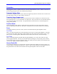
Quad Amp Hardware Reference Manual ILLUSTRATED REPAIR PARTS LIST Purpose This chapter contains the Repair Parts List (RPL) for the 4-Axis Digital Amplifier (Quad Amplifier). The RPL identifies the customer replaceable units (CRUs) of Quad Amplifier with an illustration and a Group Assembly Parts List (GAPL). Scope The GAPL includes figure/index number; part number; description; true manufacturer and true manufacturer part number, if applicable, for each CRU of the Quad Amplifier.
Quad Amp Hardware Reference Manual Figure 12 Delta Tau Data Systems 4 Axis Digital Amplifier 34 Illustrated Repair Parts List
Quad Amp Hardware Reference Manual Part Number Description Figure 1 2 3 4 5 6 7 And Index Number 7-1 -10 -20 -30 -40 -50 -60 -70 -80 -90 -100 -110 -120 -130 -140 -150 -160 -170 500-602645-103 QUAD Digital Amplifier (Top Assy) 300-602761-103 PCBA, Logic I/O 400-602800-103 Soft Start Assy 300-602677-102 PCBA, Current Sense 200-602617-556 Amplifier Cover 200-602737-551 Plastic Cover (Motor Output) 200-602816-552 Plastic Cover (AC Input Voltage) 007-400182-008 Capacitor 1800UF/400V 021-HPFRR1000 021-TK30R0214
Quad Amp Hardware Reference Manual Part Number Description Figure 1 2 3 4 5 6 7 And Index Number -270 014-030M03HSM -280 014-00MF040HM -290 300-603001-100 -300 300-603000-100 -310 300-603000-100 -320 016-600V0455A -330 016-MARA070TB -340 016-000012-600 -350 028-08A180NCS -360 301-602815-101 -370 301-602815-101 -380 200-602625-554 -390 200-602626-554 36 Qty Per Assy Manufacturer Part Number 3 Pos. Plug (P2) 1 Amp 1-480700-0 4 Pos.