
User's Manual


UMAC CPCI Accessory Cx Family
Connections 3
CONNECTIONS
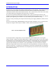
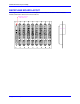
In a typical configuration, the Acc-Cx Compact UBUS backplane board is installed into a standard 3U-
format Eurorack with screws and the 3U-format UMAC CPCI boards are slid into the rack so that their J1
and J2 rear connectors mate with the P1-n and P2-n connectors on the front side of the backplane board.
A rack-mounted power supply is installed into the P47-style power connector and the power source is
connected into the rear-side J1 connector. Distribution boards or cables for the field wiring are connected
to the rear-side P2-n connectors.
In a typical installation, the UMAC CPCI CPU board is simply slid into a slot of a 3U-Eurocard rack until
it inserts into the mating connectors on the backplane board already installed in the rack. In actual
operation, all signals to the board come into the CPU board through the backplane. (The front-panel RS-
232 connector is intended for test and debugging purposes.)
Compact UBUS Connectors
The P1-n Compact UBUS connectors along the bottom half of the front side of the backplane board
provide the means for the UMAC CPCI CPU board to communicate with axis and I/O boards through the
backplane. They also provide the 3.3V and 5V (and optionally the +/-12V) power supply lines to the 3U-
format boards. Matching pins on all P1-n (n = 1 to x on an Acc-Cx board) connectors are bussed
together.
Because of the design of the Compact UBUS, the CPU board can operate in any slot of the bus.
However, if the CPU board has the CPCI bridge board installed on it, the CPU board must be installed in
the end slot of the Compact UBUS backplane immediately adjacent to the Compact PCI bus backplane
board, so the bridge board can be installed in the adjacent CPCI end slot.
Field Wiring Connectors
The P2-n field-wiring connectors at the top of the back edge of the board provide the path for all of the
signals between each 3U-format board and the outside system. These are pass-through connectors, so that
the same signals are available on matching pins on the front and back of the same connector. Each P2-n
connector is electrically independent of all the other P2-n connectors. In a typical configuration, a
system-specific distribution system is installed behind the backplane for each P2-n connector used.
Power Supply Connector
The P{x+1} connector on the Acc-Cx (e.g. P9 for the 8-slot Acc-C8 board) connector is a P47-style
power-supply connector. It is designed so that standard 3U-format CPCI power supplies can be installed,
with voltage level V1 as +5V; V2 as +3.3V; V3 as +12V; and V4 as –12V.
Power-Input Connector
The J1 connector on the rear side of the Acc-Cx board opposite the power-supply connector provides the
means to bring in the power input to the UMAC CPCI system. These pins simply provide a pass-through
of the power-input to the rack-mounted power supply. Depending on the power supply used, an AC or
DC power input may be used.